
Astro Van 2WD V6-4.3L VIN X (2002)
sometimes incorrectly identify which cylinder is misfiring. The Misfire Counters graphic shows there are misfires counted from more than one cylinder.
Cylinder #1 has the majority of counted misfires. In this case, the misfire counters would identify cylinder #1 as the misfiring cylinder. The misfires in
the other counters were just background noise caused by the erratic rotation of the crankshaft. If the number of accumulated misfires is sufficient for the
diagnostic to identify a true misfire, the diagnostic will set DTC P0300 - Misfire Detected. The illustration depicts an accumulation in the history buffers.
If two cylinders in sequential firing order are both misfiring, the first misfiring cylinder will accumulate misfires in its buffer, but the second misfiring
cylinder will not. This is because the PCM compares a misfiring cylinder with the cylinder 90 degrees prior to it in the firing order. Therefore the PCM
would be comparing crankshaft speed of the second misfiring cylinder to an already suspect cylinder. The PCM however, will be able to detect both
misfiring cylinders after the engine exceeds 2,000 RPM. This is because the PCM then starts to compare misfires to the opposing cylinder rather than the
previous cylinder in the firing order.
Use Techline equipment to monitor the misfire counter data on applicable vehicles, knowing which specific cylinders misfire can lead to the root cause.
Using the information in the misfire counters identifies which cylinders are misfiring. If the counters indicate cylinders number 1 and 4 misfired, look for
a circuit or component common to both cylinders.
The misfire diagnostic may indicate a fault due to a temporary fault not necessarily caused by a vehicle emission system malfunction. Examples include
the following items:
^
Contaminated fuel
^
Running out of fuel
^
Fuel fouled spark plugs
^
Basic engine fault
Oxygen Sensor Diagnosis
Diagnose the fuel control heated oxygen sensors for the following conditions:
^
Heater performance, time to activity on cold start
^
Slow response
^
Response time, time to switch R/L or L/R
^
Inactive signal, output steady at bias voltage - approximately 450 mV
^
Signal fixed high
^
Signal fixed low
Diagnose the catalyst monitor heated oxygen sensors for the following functions:
^
Heater performance, time to activity on cold start
^
Signal fixed low during steady state conditions
^
Inactive sensor
PCM Function
The PCM supplies a buffered voltage to various sensors and switches. The PCM controls most components with electronic switches which complete a
ground circuit when turned ON.
PCM Service Precautions
The PCM is designed to withstand normal current draws associated with vehicle operations. Avoid overloading any circuit. When testing for opens or
shorts, do not ground any of the PCM circuits unless instructed. When testing for opens or shorts, do not apply voltage to any of the PCM circuits unless
instructed. Only test these circuits with a DMM while the PCM connectors remain connected.
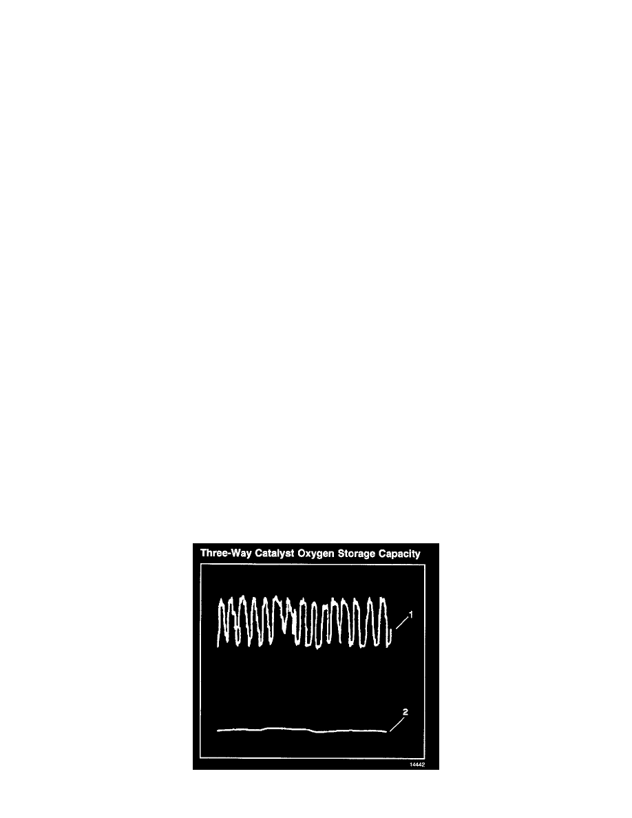
Three-Way Catalyst Oxygen Storage Capacity