
Astro Van L AWD V6-4.3L VIN W (1996)
REMOVE OR DISCONNECT
NOTE: It is possible to install the distributor driven gear in two positions. Make sure when installing the gear that the dimple found below the roll pin
hole in the gear is on the same side as the rotor segment. The dimple will not align directly with the rotor segment. If not, the gear is installed 180
degrees off and a no start condition may occur. Premature wear and damage may result.
1. Two screws holding the cap to the housing.
2. Cap from the housing.
3. Two screws from the rotor.
4. Rotor.
^
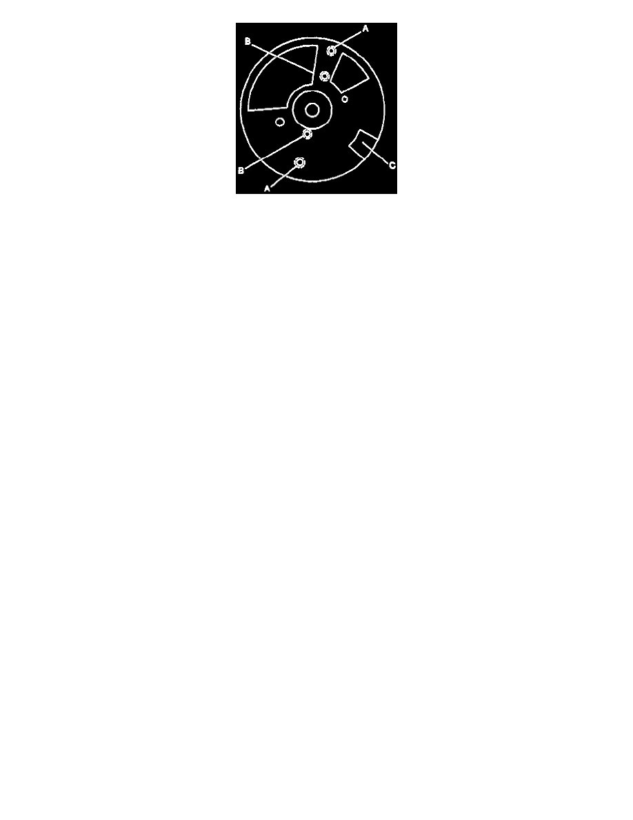
Note which locating holes (B) the rotor was removed from.
5. Two screws holding the hall effect switch.
6. Hall effect switch.
^
The square cut hole (C) in the vane wheel must be aligned with the hall effect switch in order to remove the hall effect switch.
7. Roll pin from the shaft.
^
Note the dimple located below the roll pin hole on the one side of the gear. The dimple will be used to properly orient the gear on the shaft
during assembly.
8. Driven gear, washer, and tang washer.
9. Shaft.
If the shaft can't be removed from the distributor housing due to varnish buildup, use a cloth dampened with varnish remover to clean the shaft.
NOTE: Failure to keep cleaning agents away from the hall effect switch may result In premature failure.
INSPECT
1. Cap for cracks, tiny holes or carbon tracks between cap terminal traces. Carbon tracks can be diagnosed by using an ohmmeter. With the cap
removed, place one base ohmmeter lead on a cap terminal. Use the other lead to probe all other terminals and the center carbon ball. Move the
base lead to the next terminal and probe all other leads. Continue until all secondary terminals have been tested. If there are any non-infinite
readings, replace the cap.
2. Cap for excessive build up of corrosion on the terminals. Scrape them clean or replace the cap. Some build up is normal.
3. Rotor segment. Replace the rotor if there is excessive wear on the rotor segment. Some looseness of the rotor segment is normal and does not
cause performance problems.
4. Shaft for shaft-to-bushing looseness. Insert the shaft in the housing. If the shaft wobbles, replace the housing assembly.
5. Housing for cracks or damage.
INSTALL OR CONNECT
1. Hall effect switch.
2. Two screws holding the hall effect switch. Do not overtighten the screws as the base may strip.
3. Shaft.
4. Tang washer, washer, and driven gear.
When the driven gear is properly installed the dimple located below the roll pin hole, in the driven gear, will be on the same side as the rotor
segment when the rotor is installed in the distributor. The alignment will not be exact. If the driven gear is installed incorrectly, the dimple will be
approximately 180 degrees opposite the rotor segment when the rotor is installed in the distributor.
5. Roll pin.
6. Rotor.
^
"A" shows the mounting holes. "B" shows the locating holes.
7. Two screws holding rotor. Tighten Screws to 2 Nm (20 lb. in.).