
Astro Van L AWD V6-4.3L VIN W (1996)
REMOVAL PROCEDURE
1. Disconnect the negative battery cable.
2. Remove the connectors from the VCM.
3. Remove the mounting hardware.
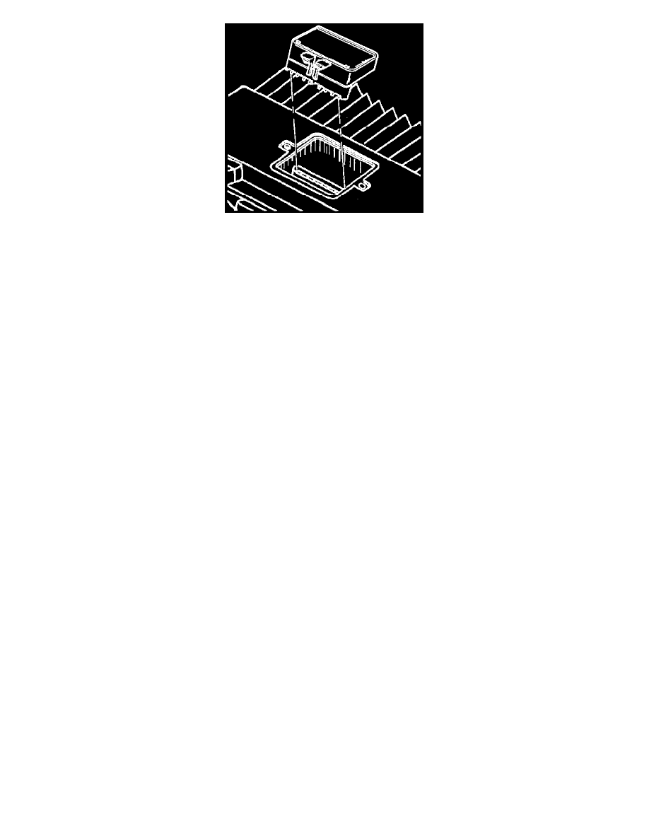
4. Remove the VCM from the engine compartment.
5. Remove the VCM access cover.
NOTE: Do not remove the cover of the KS Calibration PROM. Use of an unapproved KS Calibration PROM removal methods may cause
damage to the KS Calibration PROM or the socket.
IMPORTANT: The replacement VCM is supplied without a KS Calibration PROM so for reuse in the new VCM carefully remove the PROM
from the defective VCM.
6. Remove the Calibration PROM.
^
Using the thumb and first finger, remove the KS Calibration PROM by gently squeezing each end of the blue KS Calibration PROM. Pull
upward.
7. Inspect for the alignment notches of the KS Calibration PROM.
8. Carefully set it aside.
9. Do not open the KS Calibration PROM.
INSTALLATION PROCEDURE
IMPORTANT: Press only on the ends at the KS Calibration PROM. The small notches in the KS Calibration PROM must align with the small notches
in the KS Calibration PROM socket. Gently press on the KS Calibration PROM until it is firmly seated in the socket. Listen tar the click.
1. Install the KS Calibration PROM in the KS Calibration PROM socket.
2. Install the access cover on the VCM.
3. Install the VCM in the engine compartment.
4. Install the connectors to the VCM.
5. Connect the negative battery cable.