
Astro Van L AWD V6-4.3L VIN W (1996)
4.
Wedge large screwdriver or similar tool between pinion shaft and face of cam gear to compress gear assembly into case.
5.
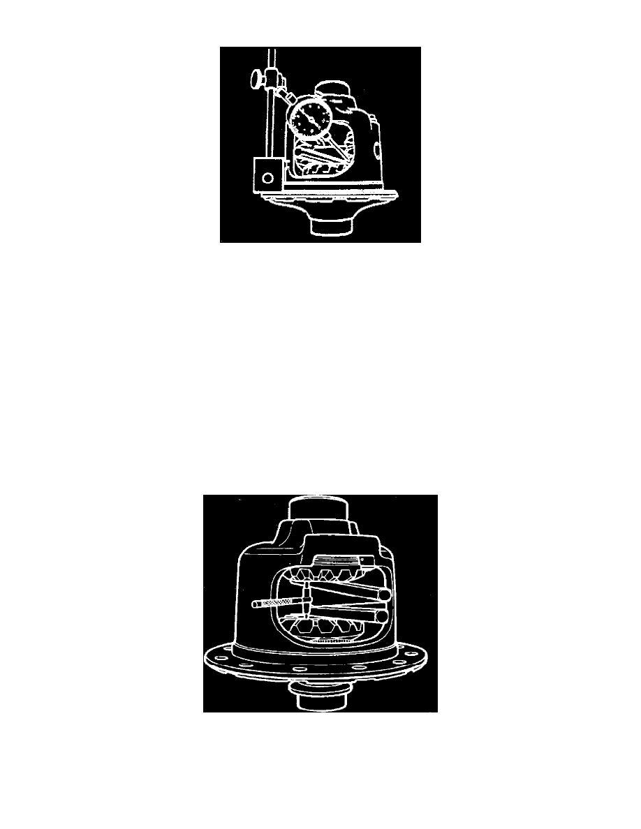
Mount suitable dial indicator on case with plunger button bearing against pinion tooth indexed in step 3,
Fig. 7.
6.
Pull pinion gear against case, rotate pinion back and forth against cam gear and read backlash from indicator.
7.
Repeat steps 3 through 6 with remaining differential pinion.
8.
Select a cam gear shim which will provide .010-.018 backlash between cam gear and differential pinions.
When cam gear and/or shim is
replaced, thrust block must be measured and selected to maintain proper clearance during assembly.
SIDE GEAR (R.H.) SHIM SELECTION
If side gear is replaced, or if original shim thickness cannot be determined, select proper side gear shim thickness by measuring backlash between
side gear and differential pinions. Follow procedure outlined for ``Cam Gear Shim Selection,'' using fully assembled side gear properly installed in
case. Select a shim that will provide .002-.010 inch backlash between side gear and differential pinions. If side gear and/or shim is replaced, refer
to
Thrust Block Selection during case assembly in order to install thrust block that will maintain proper assembly clearances. See: Corporate and
Eaton/9 1/2 Inch Ring Gear/Overhaul/Eaton Locking/Thrust Block Selection
Thrust Block Selection
If cam gear, side gear, and/or shims have been replaced, or if it is necessary to replace thrust block and original dimension cannot be determined, use
following procedure during differential case assembly to determine proper thrust block side.
1.
Install fully assembled cam and side gears in case along with selected shims.
2.
Install differential pinion shaft and secure with lock screw.
3.
Wedge large screwdrivers or similar tools between pinion shaft and cam and side gears.
Fig. 8 Side gear spread measurement. Eaton locking differential
4.
Measure distance between cam gear face and side gear face (side gear spread) using suitable gauge,
Fig. 8, and record dimension. Ensure that
gauge is ``square'' in case and that gauge bears against faces of gears, not gear teeth.
5.
Select thrust block of a thickness zero to .006 inch less than dimension measured in step 4.
Original thrust block can be reused if it is
undamaged and will provide the specified zero to .006 inch clearance. Right side gear can also be reshimmed to obtain specified thrust