
Astro Van M L4-151 2.5L (1985)
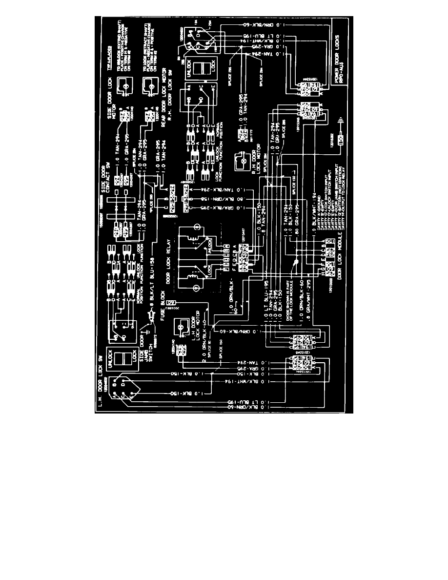
Figure 1 - SYSTEM CIRCUIT DIAGRAM
A more detailed description of the system operation follows. The system circuit diagram is shown in Figure No. 1. When either door lock switch is
placed in the "lock" position, battery voltage is applied to both front door lock motors directly through the door lock switches. Battery voltage is also
applied to the lock coil of the door lock relay, which pulls in and applies battery voltage to the circuit containing the rear door and sliding door lock
motors. If the sliding door is open when the door lock switch is operated, terminal F of the door lock delay module is grounded through the sliding door
jamb switch and terminal C is at battery voltage through the door lock switch. This combination of inputs sets a logic circuit in the door lock delay
module. Upon dosing the sliding door, the jamb switch opens removing the ground connection from terminal F. This initiates a timing cycle in the door
lock delay module and after approximately five seconds, terminal H of the module turns on, energizing the lock coil of the door lock relay and resetting
the logic circuit in the module. Battery voltage is then applied through the door lock relay to the door lock motors in the sliding door and rear door.
When either door lock switch is placed in the "unlock" position, battery voltage is applied to both front door lock motors directly through the door lock
switches. Battery voltage is also applied to
terminal D of the door lock delay module to reset the logic circuit and to the unlock coil of the door lock relay, which pulls in and applies battery voltage
to the circuit containing the rear door and sliding door lock motors.
POWER DOOR LOCK SYSTEM FAULT DIAGNOSIS