
Astro Van M V6-262 4.3L VIN B TBI (1991)
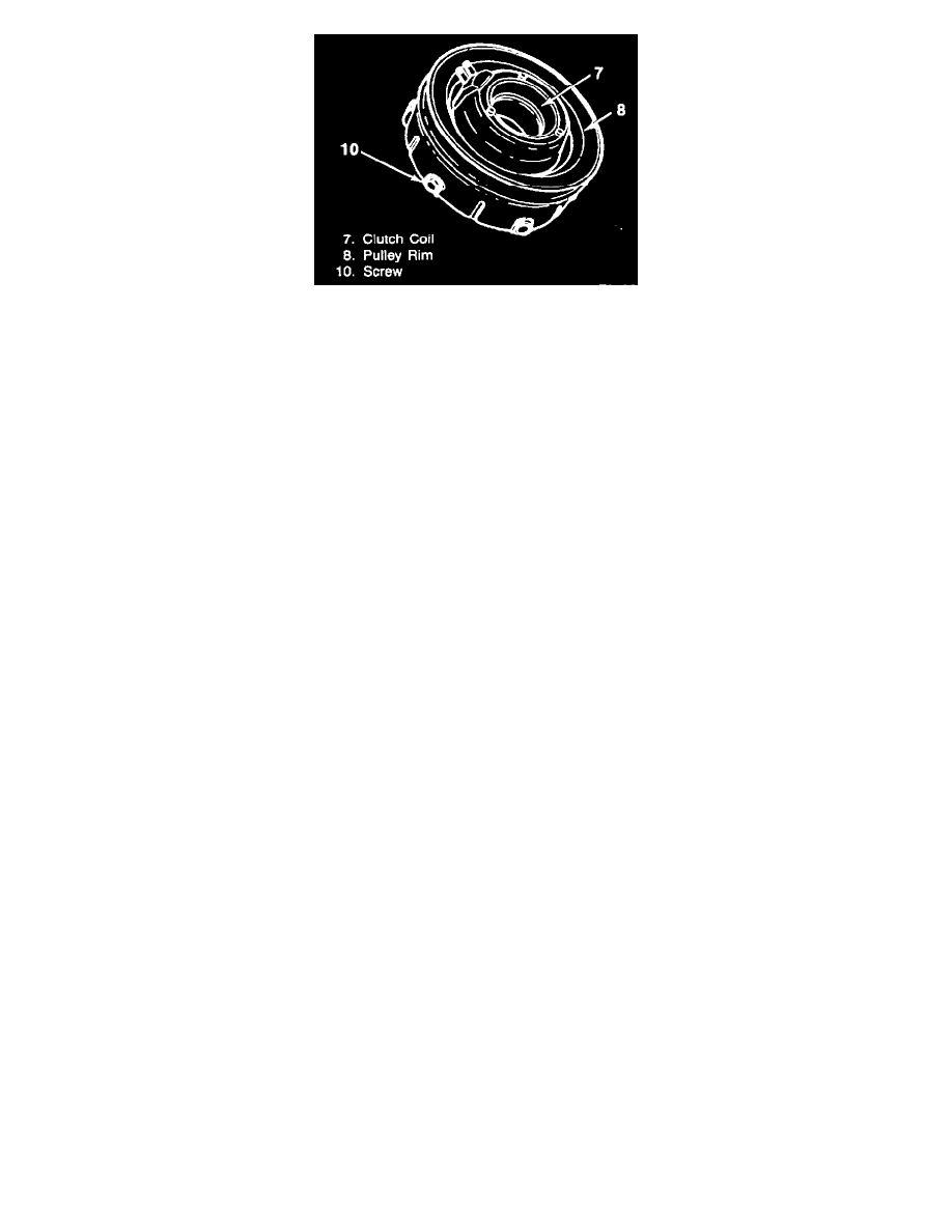
Assembling Clutch Coil, Pulley Rim, Rotor & Bearing Assembly
1. Clutch coil, pulley rim, clutch rotor and bearing assembly.
Important
^
Use new screws and apply Loctite 601 or equivalent to the screw threads, but do not tighten.
2. Place the assembly on the neck of the front head and seat into place using J 26271-A.
^
Before fully seating the assembly, place the clutch coil terminals in relation to the compressor. Align the three protrusions on the rear of the
clutch coil with the locator holes in the front head.
3. Rotor and bearing retainer ring (4) and reassemble the clutch plate and hub assembly as described in "Clutch Plate and Hub Assembly
Replacement!'
4. Rotate the pulley rim (8) and rotor (5) to be sure the pulley rim (8) is rotating "in-line" and adjust as required.
Inspect
^
Clutch plate to clutch rotor gap is 0.5 to 1.0 mm (0.020 to 0.040-inches).
Tighten
^
Pulley rim mounting screws (10) to 11 N.m (100 in. lbs.).
5. Bend the lock washers (9) to secure the screws (10).
Poly-Groove Drive