
Astro Van M V6-262 4.3L VIN Z (1994)
EGR Electronic Vacuum Regulator Solenoid: Description and Operation
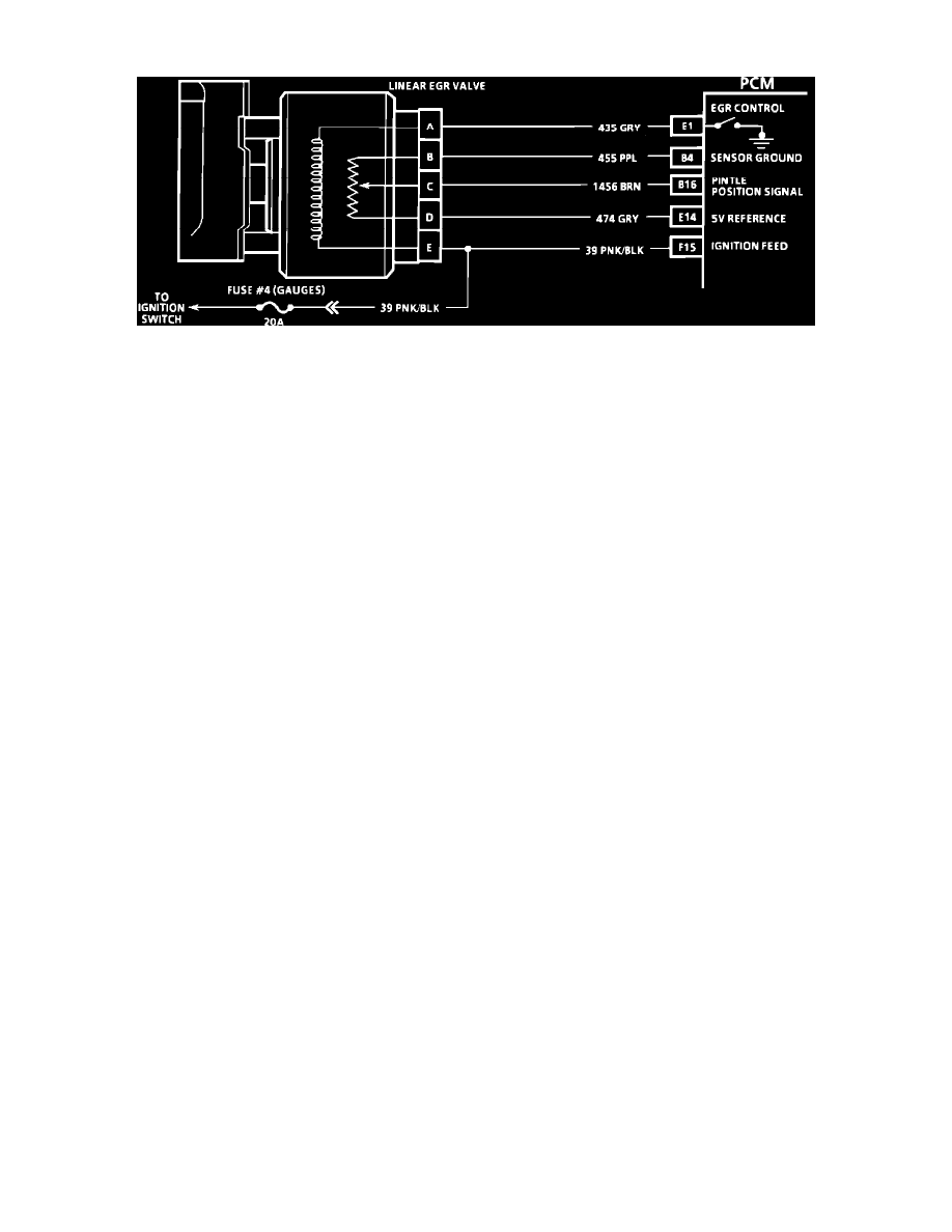
Exhaust Gas Recirculation (EGR) System Circuit Diagram
PURPOSE
The exhaust gas recirculation (EGR) system is used to reduce oxides of nitrogen (NOx) emissions. The atmosphere is made up of mostly Nitrogen,
with a smaller percentage of oxygen, and a mixture of other gases. Oxygen and Nitrogen do not normally combine except at very high
temperatures and pressures, conditions which are present in the combustion chamber especially during hard acceleration. When the engine is under
load, the EGR valve admits a small amount of exhaust gas into the intake manifold to mix with the air/fuel charge. The exhaust gas is essentially
inert (contains no fuel or oxidizer) and reduces peak combustion temperatures and pressures by absorbing some of the heat of combustion without
participating in the actual burn. Greater amounts of exhaust gas are metered in as engine speed and load are increased.
The linear EGR valve is designed to accurately supply regulated amounts of exhaust gas to the intake manifold, independent of manifold vacuum.
OPERATION
The linear EGR valve gets battery power when the ignition is turned "ON" and becomes energized when the control module completes the circuit
to ground. When a solenoid is energized, the armature, with attached shaft and swivel pintle, is lifted and the orifice is opened. The linear EGR
valve uses a potentiometer to measure the amount of valve opening. The PCM utilizes Pulse Width Modulation (PWM) to control EGR operation.
When the necessary conditions are met for EGR operation the PCM closes the ground switch to the EGR valve, the EGR pintle position sensor
relays the current EGR orifice opening to the PCM. The PCM then varies the PWM until the actual orifice opening matches the desired orifice
opening.
The PCM uses the information from the the following sensors to control the flow:
1. Coolant temperature (CTS)
2. Throttle Position Sensor (TPS)
3. Manifold Absolute Pressure (MAP)
4. Barometric (BARO) Pressure
5. PRNDL Switch position
6. Pintle Position Sensor
CONSTRUCTION
The pintle that closes the EGR orifice is attached directly to the solenoid shaft with. The effects of EGR leakage on idle quality are reduced
because the shaft and seals are exposed to the exhaust pressure instead of manifold vacuum. The shaft is sealed from the exhaust chamber by a
floating seal held in place by the seal spring. This spring also holds the upper seal of the armature cavity in the solenoid.