
Avalanche 2500 4WD V8-8.1L VIN G (2003)
- J 41013 Rotor Resurfacing Kit
- J 42450-A Wheel Hub Resurfacing Kit
1. Release the park brake.
2. Raise and suitably support the vehicle. Refer to Lifting and Jacking the Vehicle in General Information.
3. Remove the tire and wheel assembly. Refer to Tire and Wheel Removal and Installation in Tires and Wheels.
4. Mark the relationship of the rotor to the axle flange.
5. Install a C-clamp over the body of the brake caliper, with the C-clamp ends against the rear of the caliper body and the outboard disc brake pad.
6. Slowly tighten the C-clamp until the pistons are pushed into the caliper bores enough to remove the caliper from the pads.
7. Remove the C-clamp from the caliper.
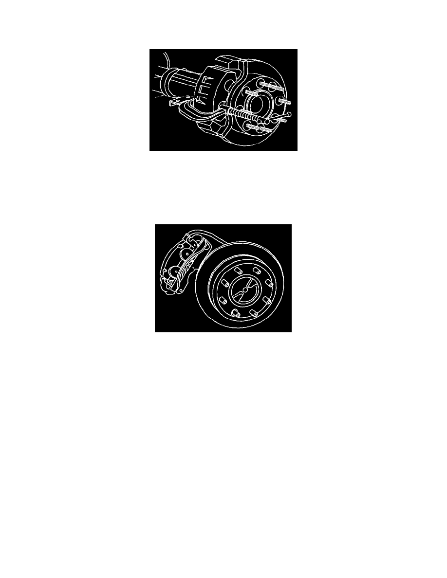
8. Remove the brake caliper bracket mounting bolts.
Note: Support the brake caliper with heavy mechanic's wire, or equivalent, whenever it is separated from it's mount and the hydraulic flexible
brake hose is still connected. Failure to support the caliper in this manner will cause the flexible brake hose to bear the weight of the caliper,
which may cause damage to the brake hose and in turn may cause a brake fluid leak.
9. Remove the brake caliper and brake caliper bracket as an assembly and support with heavy mechanic's wire or equivalent. DO NOT disconnect the
hydraulic brake flexible hose from the caliper.
10. Remove the rotor retaining push nuts from the wheel studs, if applicable.
11. It may be necessary to strike the end of the hub or the rotor with a deadblow hammer to separate the rotor from the hub.