
Avalanche 2500 4WD V8-8.1L VIN G (2003)
^
J8614-01 Flange/Pulley Holding Tool
^
J22388 Pinion Oil Seal Installer - Rear (8.6 inch, 9.5 inch axle)
^
J44414 Pinion Seal Installer (10.5 inch axle)
Removal Procedure
Important: Observe and mark the positions of all the driveline components, relative to the propeller shaft and the axles, prior to disassembly. These
components include the propeller shafts, drive axles, pinion flanges, output shafts, etc. Reassemble all the components in the exact places in which you
removed the parts. Follow any specifications, torque values, and any measurements made prior to disassembly.
1. Raise the vehicle. Refer to Vehicle Lifting.
2. Remove the tire and wheel assemblies (8.6 inch, 9.5 inch axles).
3. Remove the rear brake calipers.
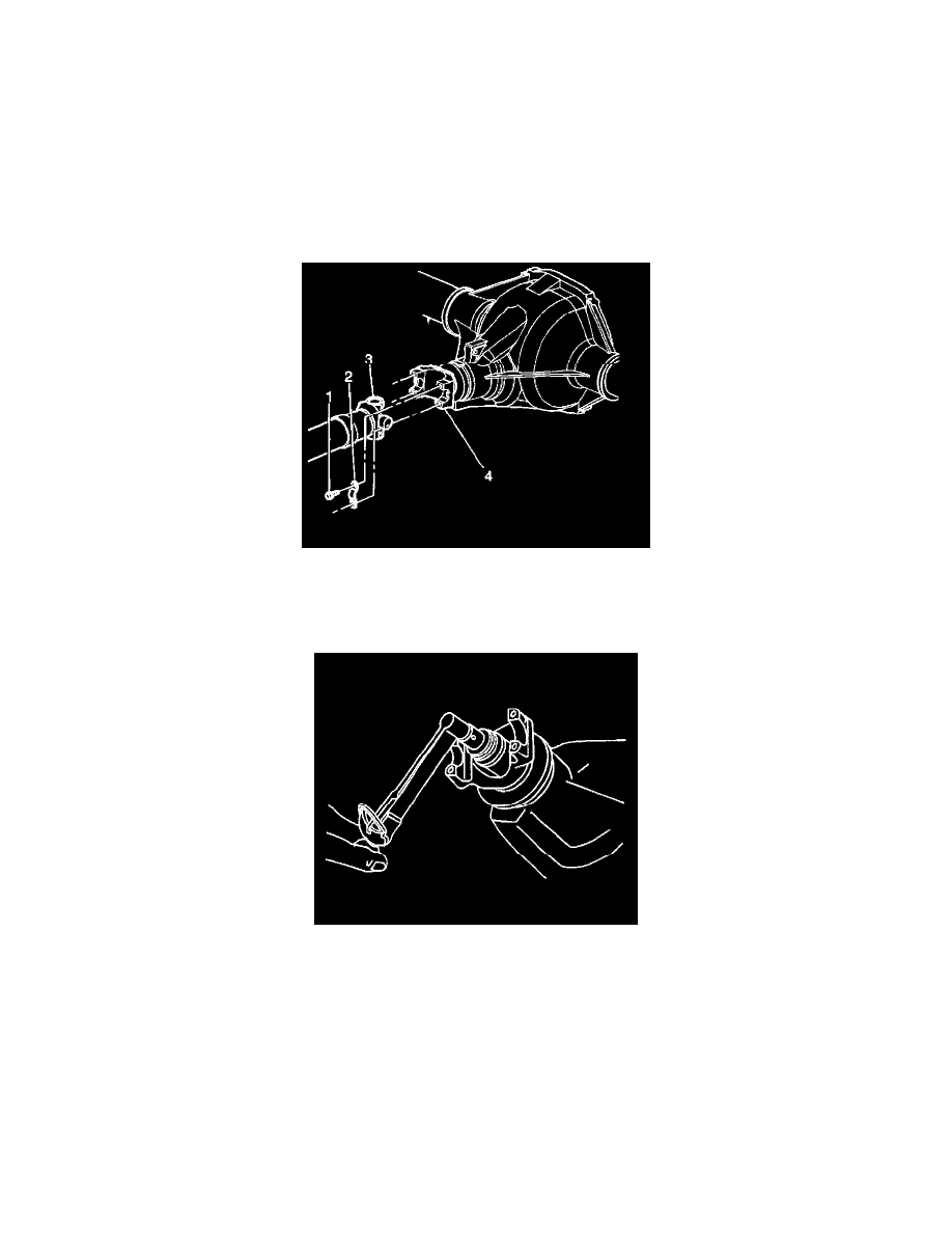
6. Reference mark the rear propeller shaft (3) to the rear axle pinion yoke (4).
7. Disconnect the propeller shaft from the axle.
Wrap the bearing caps with tape in order to prevent the loss of bearing rollers.
Support the propeller shaft as necessary.
8. Measure the amount of torque required to rotate the pinion. Use an inch-pound torque wrench. Record this measurement for reassembly. This will
give the combined preload for these components:
^
The pinion bearings
^
The pinion pilot bearing (10.5 inch axle)
^
The pinion oil seal
^
The differential case bearings
^
The axle bearings (8.6 inch, 9.5 inch axles)
^
The axle seals (8.6 inch, 9.5 inch axles)
9. Draw 2 arrows pointing at each other, one on the pinion stem, the other on the pinion yoke.
10. Record the number of exposed threads on the pinion stem for reference.