
Beretta L4-121 2.0L (1987)
Installation of Afterblow Module
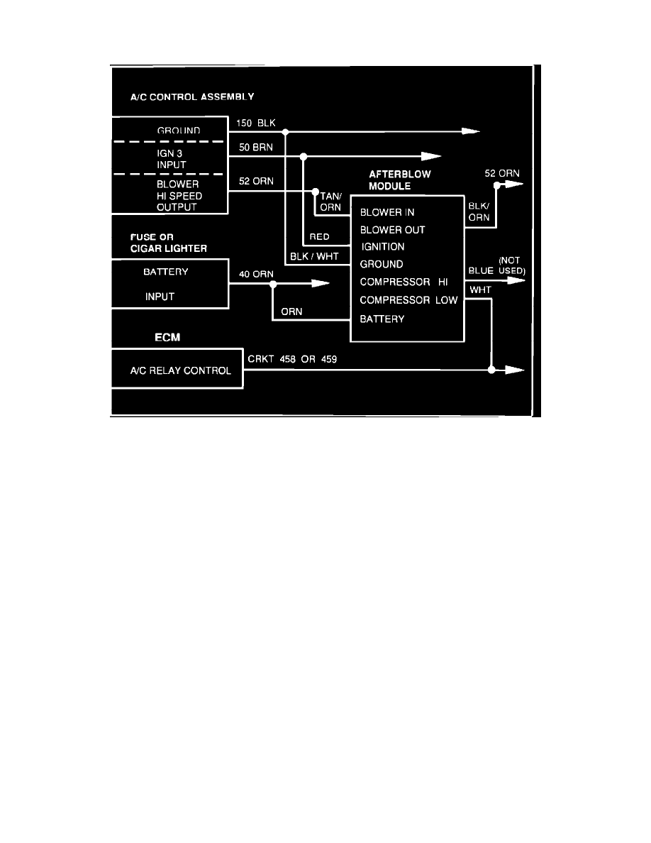
FIGURE 3 CIRCUIT DIAGRAM
THE FOLLOWING STEPS ARE THE INSTRUCTIONS FOR THE INSTALLATION OF THE AFTERBLOW MODULE.
Important!
The afterblow module will enable the blower to run at high speed for five
(5)
minutes approximately fifty (50) minutes after the vehicle ignition is turned off, if the compressor was engaged for four (4) minutes or more
during the last ignition cycle.
Important!
All the connections of the afterblow harness to the vehicle wiring should be
spliced, using the proper techniques shown in Section 8A of the appropriate Service Manual. The splices should be made using
splice clips, solder and wrapping the splice with electrical tape. Do not use instant connectors such as 3M's "SCOTCHLOK" brand.
Important!
The circuit diagram shown in Figure 3 shows the circuit numbers generally
used on the subject model year car lines. However, to make sure of the correct circuits and wire colors are spliced into, refer to
Section 8A of the appropriate Service Manual.
18.
Disconnect the negative battery cable.
19.
Remove close out panels, fuse block, trim plates, A/C control head and glove box as required to gain access to the circuits shown in the
circuit diagram. Refer to Section 8A of the appropriate Service Manual for component location and service procedures.
20.
Disconnect the afterblow module from its jumper harness and set the module aside.
21.
Splice the black/white wire (PIN C) of the harness into the black ground wire of the A/C control head wiring (circuit # 150).
22.
Splice the orange wire (PIN A) of the harness to a battery feed at the fuse block or the cigar lighter (circuit # 40).
23.
Splice the red wire (PIN B) of the harness to the ignition feed wire of A/C control head wiring (circuit # 50).
24.
Cut the orange high speed blower output wire (circuit # 52) of the A/C control wiring. Splice the tan/orange wire (PIN F) of the harness to the
orange wire leading to the A/ C control head. Splice the black/orange wire (PIN G) of the harness to the other end of the orange wire leading
to the blower motor.