
Beretta L4-138 2.3L DOHC QUAD 4 (1991)
Wiring Diagram
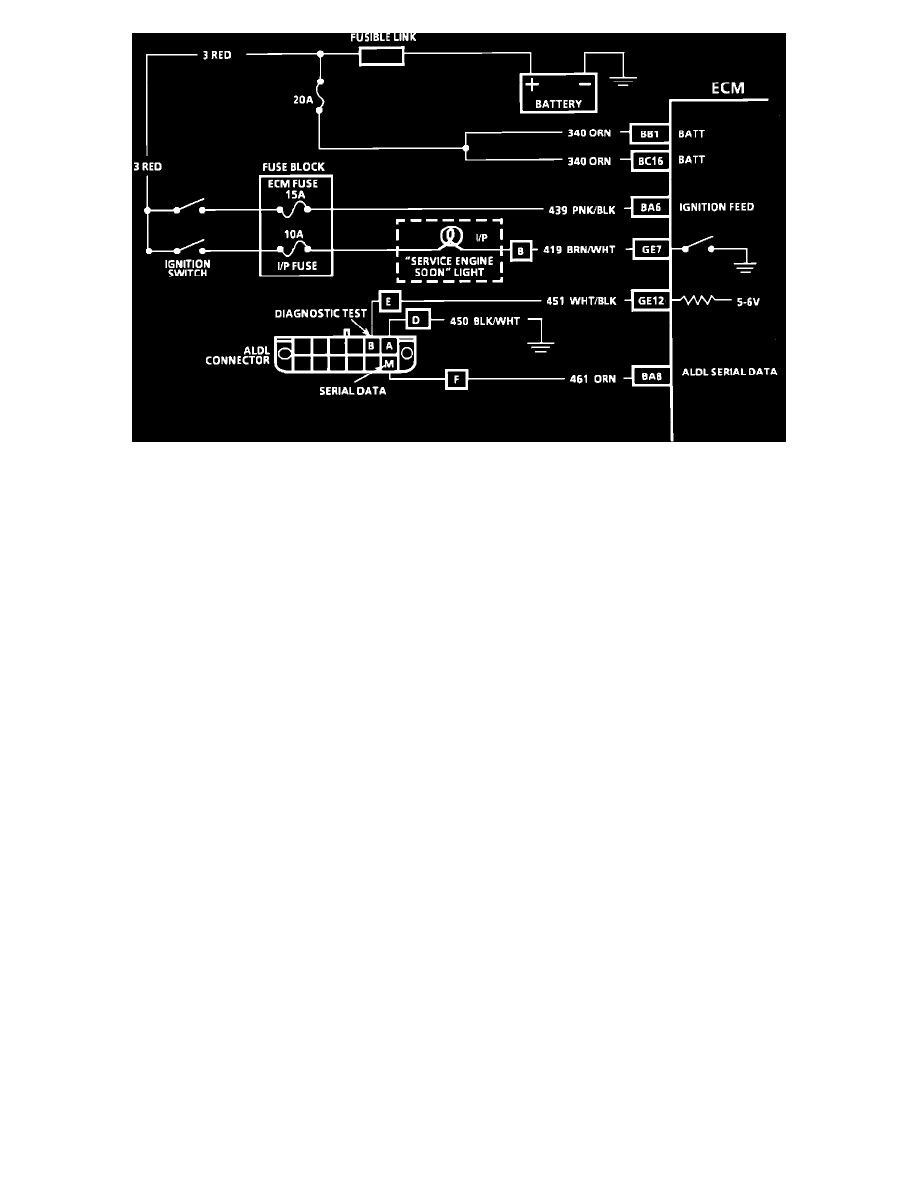
CIRCUIT DESCRIPTION:
There should always be a steady "SERVICE ENGINE SOON" light when the ignition is "ON" and engine stopped. Battery voltage is supplied through
the ignition switch directly to the light bulb. The electronic control module (ECM) controls the light and turns it "ON" by providing a ground path
through CKT 419 to the ECM.
TEST DESCRIPTION:Numbers below refer to circled numbers on the diagnostic chart.
1.
If the fusible link is blown, locate and repair short to ground.
2.
Using a test light connected to 12V (B+) probe each of the system ground circuits to be sure a good ground is present. See SCHEMATIC
DIAGRAMS/ELECTRICAL AND ELECTRONIC DIAGRAMS/ECM CONNECTOR DIAGRAMS for ECM pin locations of ground
circuits.
DIAGNOSTIC AIDS:
Engine runs OK, check:
^
Faulty light bulb.
^
CKT 419 open.
^
IP fuse blown; this will result in the loss of "SES" light, oil light, brake light, etc. on IP.
Engine cranks but will not run:
^
Continuous battery - fuse or fusible link open.
^
ECM ignition fuse open.
^
Battery CKT 340 to ECM open.
^
Ignition CKT 439 to ECM open.
^
Poor connection to ECM.
^
Poor ECM ground.