
Beretta L4-138 2.3L DOHC QUAD 4 HO MFI VIN A (1994)
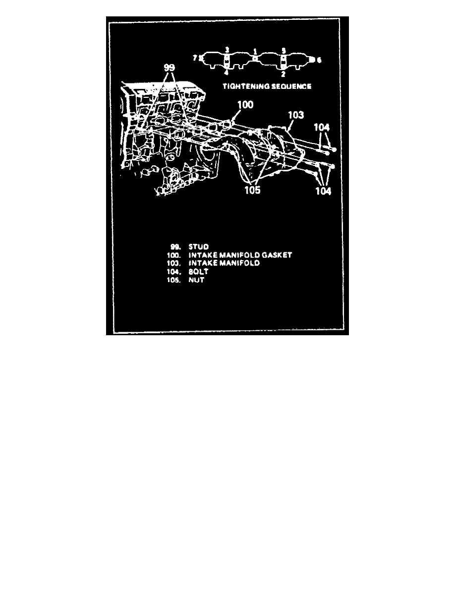
Fig. 8 Intake Manifold Replacement
1. Disconnect battery ground cable.
2. Drain cooling system.
3. Disconnect MAP sensor electrical connector and vacuum hose.
4. Disconnect MAT sensor, purge solenoid, and fuel injector harness electrical connectors.
5. Disconnect intake manifold vacuum hoses.
6. Disconnect fuel regulator, and purge solenoid-to-canister hoses.
7. Remove throttle body-to-air cleaner duct, then separate vent tube from duct.
8. Remove accelerator cable bracket.
9. Remove brake booster vacuum hose, along with retaining bracket to power steering bracket.
10. Disconnect throttle body coolant lines.
11. Remove oil Air separator with hoses, Fig. 6 . Disconnect hoses from oil filler, chain cover, intake duct, and intake manifold.
12. Remove oil filler cap/level indicator assembly from filler tube.
13. Remove bolt/screw retaining oil filler tube to engine. Pull tube upward to separate it from block.
14. Disconnect injector harness electrical connector.
15. Remove oil filler tube by pulling upward while rotating it between intake tubes and fuel rail electrical harness. Discard oil filler tube O-ring.
16. Remove intake manifold support brace, Fig.7.
17. Remove five bolts and two nuts retaining intake manifold, Fig. 8 .
18. Remove intake manifold and gasket.
19. Reverse procedure to install noting following:
a. Install intake manifold with new gasket. Ensure numbers stamped on gasket face manifold surface. Tighten to specifications in sequence, Fig.
8 .
b. Install a new O-ring to oil filler tube. Refer to Fig. 6 when installing oil filler tube to engine.