
Beretta L4-138 2.3L DOHC QUAD 4 HO MFI VIN A (1994)
Blower Motor: Initial Inspection and Diagnostic Overview
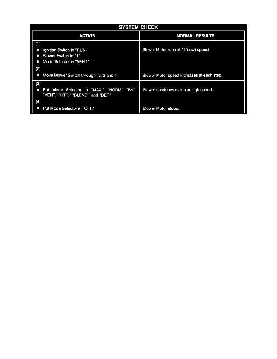
System Check
Circuit Operation
The Blower Motor circuit employs the following components:
Blower Motor
Blower Resistor Assembly
Blower Switch
Blower Motor Relay
Mode Selector
With the Ignition Switch in "RUN," battery voltage is applied to the Mode Selector. The Mode Selector funnels power to the Blower Switch in all modes
but "OFF." With the Blower Switch set to "1," battery voltage is applied to the Blower Motor though the Blower Resistor Assembly and the normally
closed contacts of the Blower Motor Relay. The Blower Motor runs at low speed. When the Blower Switch is in the "2" or "3" positions, the operation is
similar to the operation in "1" except the resistance through the Blower Resistor Assembly is decreased, causing the Blower Motor to run faster in "2"
and even faster in "3." When "4" blower speed is selected, the Blower Switch applies voltage to the Blower Motor Relay coil. The Blower Relay Motor
is energized, applying voltage from CKT 2 through the relay directly to the Blower Motor. The Blower Motor then runs at high speed.
Troubleshooting Hints
PERFORM BEFORE BEGINNING SYSTEM DIAGNOSIS
1. If the Blower Motor does not operate, check Fuse 8 by visual inspection.
2. If the Blower Motor does not operate, check that ground G101 is clean and tight.
3. If the Blower Motor runs all of the time with the Ignition Switch in "OFF," replace the Blower Motor Relay.
4. If the Blower Motor runs with the Ignition Switch in "RUN" and Mode Selector in "OFF," replace the Mode Selector.
5. Replace the Mode Selector if the Blower Motor runs with the Mode Ignition Switch in "RUN" and the Selector in one but not all of the following
modes: "MAX," "NORM," "B/L," "VENT" "BLEND," "HTR" and "DEF".
^
Refer to System Diagnosis.
Circuit Operation
BLOWER CONTROL
The Blower Motor circuit employs the following components:
Blower Motor
Blower Resistor Assembly
Blower Switch
Blower Motor Relay
Mode Selector
With the Ignition Switch in "RUN," battery voltage is applied to the Mode Selector. The Mode Selector funnels power to the Blower Switch in all
modes but "OFF." With the Blower Switch set to "1," battery voltage is applied to the Blower Motor though the Blower Motor Resistor Assembly
and the normally closed contacts of the Blower Motor Relay. The Blower Motor runs at low speed. When the Blower Switch is in the "2" or "3"
positions, the operation is similar to the operation in except the resistance through the Blower Motor Resistor Assembly is decreased, causing the
Blower Motor to run faster in "2" and even faster in "3." When "4" blower speed is selected, the Blower Switch applies voltage to the Blower