
Beretta L4-138 2.3L DOHC QUAD 4 HO MFI VIN A (1994)
A/C Signal: Description and Operation
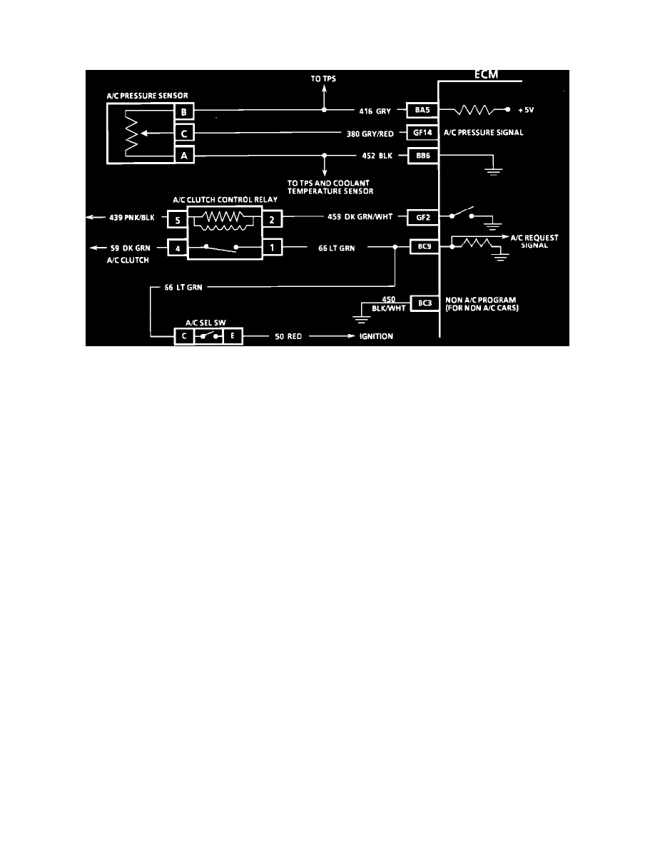
A/C on Signal
Wiring Diagram (A/C Clutch Control Circuit)
NOTE: Because different models and engine applications vary in wire colors, circuit numbers, and pin numbers, the above image is a typical example.
Refer to COMPUTERS AND CONTROL SYSTEMS/SCHEMATIC AND ROUTING DIAGRAMS for specific schematic applications.
PURPOSE
This signal indicates that the A/C control switch is turned "ON" and the pressure switch is closed.
OPERATION
The ECM/PCM uses this signal to adjust the idle speed, and on some models engages the A/C compressor clutch. If this signal is not available to
the ECM/PCM, the engine idle may be rough when the A/C compressor cycles. In some cases the A/C compressor will be inoperative.