
Beretta L4-138 2.3L DOHC QUAD 4 HO MFI VIN A (1994)
A/C Signal: Description and Operation
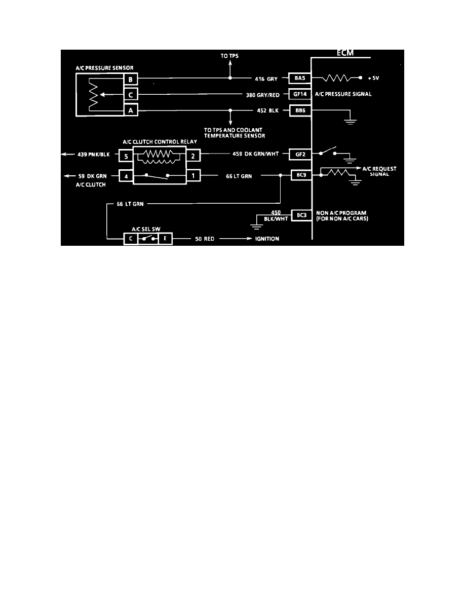
A/C Pressure Sensor
Wiring Diagram (A/C Clutch Control Circuit)
NOTE: Because different models and engine applications vary in wire colors, circuit numbers, and pin numbers, the above image is a typical example.
Refer to COMPUTERS AND CONTROL SYSTEMS/SCHEMATIC AND ROUTING DIAGRAMS for specific schematic applications.
PURPOSE
The A/C pressure sensor provides a signal to the ECM which indicates varying high side refrigerant pressure between approximately 0.0 psi to 450
psi. The ECM uses this input to determine A/C compressor load on the engine to help control idle speed with the Idle Air Control (IAC) Valve.
OPERATION
The A/C pressure sensor electrical circuit consist of a 5.0 volt reference line, a ground, and a signal wire to the ECM. The signal is a voltage that
varies from approximately 0.1 volts at 0.0 psi to 4.9 volts at 450 psi or more. A problem with the A/C pressure circuits or sensor should set a Code
66 and will make the A/C compressor inoperative.
LOCATION
High side pressure line between the compressor and the condenser.