
Beretta L4-138 2.3L DOHC QUAD 4 HO MFI VIN A (1994)
Electronic Spark Timing: Description and Operation
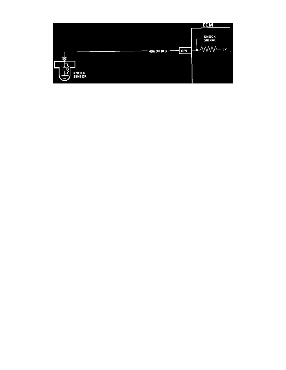
Electronic Spark Control (ESC) Diagram
NOTE: Because different models and engine applications vary in wire colors, circuit numbers, and pin numbers, the above image is a typical example.
Refer to COMPUTERS AND CONTROL SYSTEMS/SCHEMATIC AND ROUTING DIAGRAMS for specific schematic applications.
PURPOSE
The Knock Sensor (KS) retards spark timing up to 15° to reduce spark knock.
OPERATION
The KS has two major components:
-
KS module (part of MEM-CAL)
-
Knock Sensor
The knock sensor (KS) detects abnormal vibration (spark knocking) in the engine and produces an A/C output voltage which increases with the
severity of the knock. The A/C signal generated by the knock sensor inputs to the KS portion of the MEM-CAL which signals the PCM to adjust
timing. Resistance within the knock sensor circuit reduces the PCM 5 volts down to 2.5 volts.
LOCATION
MEM-CAL in Electronic Control Module.