
Beretta V6-191 3.1L (1990)
Ignition Switch And Actuator Installation
Dimmer Switch Rod Installation
Fig. 67 Adjusting Dimmer Switch. 1989-90 Beretta & Corsica
INSTALL OR CONNECT
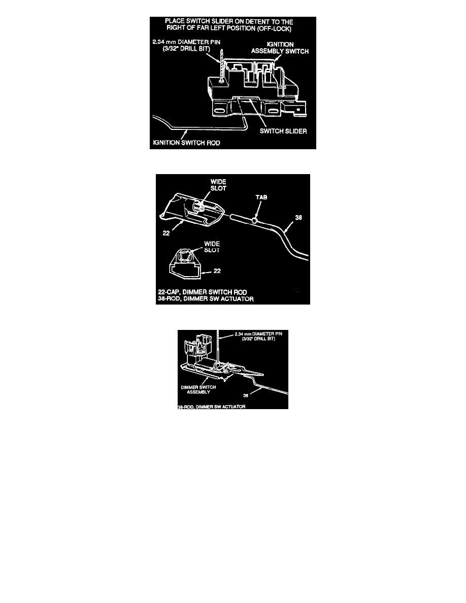
1. Place the ignition switch slider in the far left position and move back one detent to the right, "Off-Lock" position.
IMPORTANT
Insert a 2.34 mm diameter pin (3/32' drill bit) in adjustment hole on ignition switch to hold switch slider in proper position during installation.
2. Ignition switch (43) to switch rod (31).
3. Ignition switch (43) to jacket and bowl assembly (24) with mounting stud (42) and torque to 4 Nm (35 Lbs. In.).
4. Remove adjustment tool from ignition switch (43).
5. Dimmer switch actuator rod (38), tab end first, into hole in dimmer switch rod cap (22) as shown.
Note: Tab on rod (38) must engage wide slot in rod cap (22) and snap in place.
6. Dimmer switch (41) onto actuator rod (38).
7. Dimmer switch assembly (41) on stud (42) with hexagon nut (40) and screw (39). Do not tighten.
IMPORTANT
To adjust dimmer switch, insert a 2.34 mm diameter pin (3/32" drill bit). Push switch against actuator rod (38) to remove all lash.