
Beretta V6-3100 3.1L VIN M SFI (1995)
Brake Warning Indicator: Initial Inspection and Diagnostic Overview
Circuit Operation
Battery voltage is applied to the BRAKE Indicator when the Ignition Switch is in "RUN," "BULB TEST" or "START." Three switches are connected to
the BRAKE Indicator. When any one of these switches closes, ground is provided and the indicator lights.
The Ignition Switch provides a ground when it is in the "BULB TEST" and "START" positions.
The Park Brake Switch provides a ground when the Park Brake is applied.
The Brake Fluid Level Switch closes to light the BRAKE Indicator when there is low brake fluid in one of the two hydraulic brake systems. This could
be caused by a leak in one of the brake lines. The switch can be reset to an open position by refilling the reservoir; however, this can only be
accomplished after the faulty system has been repaired.
The Electronic Brake Control Module (EBCM) will cause the BRAKE Indicator to light only when the Antilock Brake system degrades the base brake
system.
System Diagnosis
^
Perform the System Check and refer to the Symptom Table for the appropriate diagnostic procedures. See: System Check See: Symptom
Related Diagnostic Procedures/Symptom Table
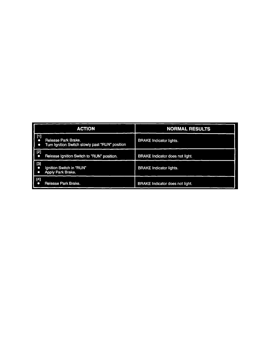
System Check
Troubleshooting Hints
Perform before beginning System Diagnosis
1. Check Fuse 9 by observing Malfunction Indicator Lamp Indicator with Ignition Switch in "RUN" and engine off.
2. Check Ground G101 by operating Blower Motor.
3. With T61: If setting Park Brake does not force BRAKE Indicator to light, check CKT 33 and Park Brake Switch. If all are OK, replace the DRL
Module.
4. If BRAKE Indicator does not light for a particular condition, check suspect switch, CKT 33 and CKT 150. Replace/repair as necessary.
^
Check for a broken (or partially broken) wire inside of the insulation which could cause system failure but prove "GOOD" in a continuity/voltage
check (Refer to "Diagnostic Aids/General Troubleshooting Procedures") See: Diagrams/Diagnostic Aids
^
Check for proper installation of aftermarket electronic equipment which may affect the integrity of other systems (Refer to "Diagnostic
Aids/General Troubleshooting Procedures") See: Diagrams/Diagnostic Aids
^
Refer to System Diagnosis. See: System Diagnosis