
Beretta V6-3100 3.1L VIN M SFI (1995)
Knock Sensor: Description and Operation
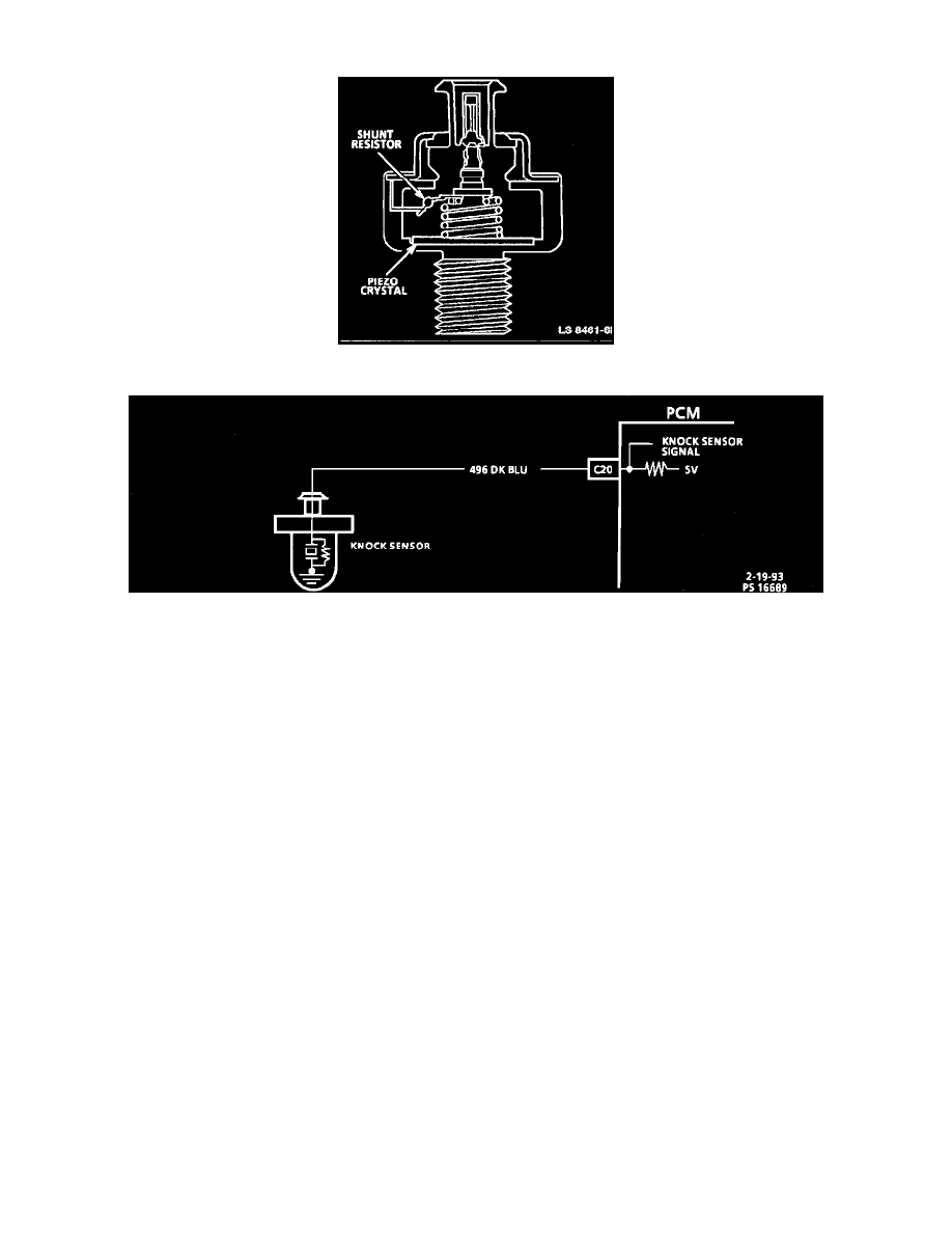
Knock Sensor (KS)
Knock Sensor Circuit Diagram
PURPOSE
Varying octane levels in today's gasoline can cause detonation in high performance engines. Detonation is sometimes called spark knock.
To control spark knock a Knock Sensor (KS) system is used. This system is designed to retard spark timing up to 10° to reduce spark knock in the
engine. This allows the engine to use maximum spark advance to improve driveability and fuel economy
OPERATION
The KS system has two major components:
^
KS module (located in the Powertrain control Module (PCM).
^
Check KS.
The KS detects abnormal vibration (spark knocking) in the engine. The sensor is mounted in the engine block near the cylinders. The sensor
produces an A/C output voltage which increases with the severity of the knock. This signal voltage inputs to the PCM. The PCM then adjusts the
Ignition Control (IC) timing to reduce spark knocking.