
Beretta V6-3100 3.1L VIN M SFI (1995)
Oxygen Sensor: Testing and Inspection
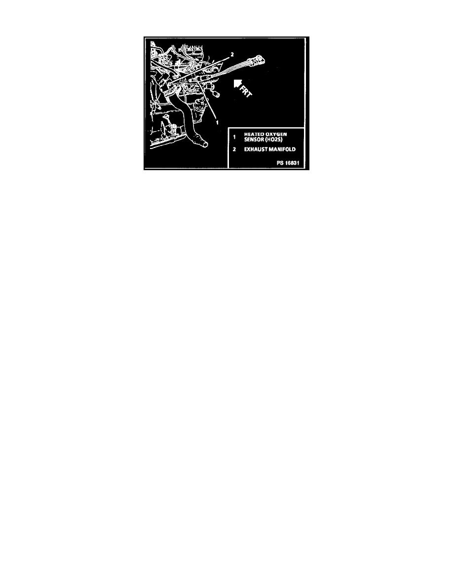
Heated Oxygen Sensor (HO2S)
DIAGNOSIS
The Tech 1 scan tool has several positions that will indicate the state of the exhaust gases, Heated Oxygen Sensor (HO2S) voltage, short term fuel
trim and long term fuel trim.
A problem in the H02S circuit, or fuel system, should set a Diagnostic Trouble Code (DTC) 13 (open circuit), DTC 44 (lean indication), DTC 45
(rich indication). Refer to applicable chart if any of these DTC(s) were stored in memory.
NOTE: The HO2S uses a permanently attached pigtail and connector. This pigtail should not be removed from the heated oxygen sensor. Damage
or removal of the pigtail or connector could affect proper operation of the oxygen sensor.
Take care when handling the HO2S. The in-line electrical connector and louvered end must be kept free of grease, dirt or other contaminants.
Also, avoid using cleaning solvents of any type. Do Not drop or roughly handle the HO2S.
REMOVE OR DISCONNECT
^
The HO2S may be difficult to remove when engine coolant temperature is less than 48°C (120°F). Excessive force may damage threads in
exhaust manifold or exhaust pipe.
1. Negative battery cable.
2. Electrical connector.
3. Carefully back out H02S using tool J 29533A/BT-8127.
INSTALL OR CONNECT
NOTE:A special anti-seize compound is used on the HO2S threads. The compound consists of a liquid graphite and glass beads. The graphite will
burn away, but the glass beads will remain making the sensor easier to remove.
New or service sensors will already have the compound applied to the threads. If a sensor is removed from an engine and if for any reason it is to
be reinstalled, the threads must have anti-seize compound applied before reinstallation.
1. Coat threads of Heated HO2S with anti-seize compound P/N 5613695, or equivalent if necessary.
2. Sensor, and torque to 41 Nm (30 lb. ft.).
3. Electrical connector.
4. Negative battery cable.