
Beretta V6-3100 3.1L VIN M SFI (1995)
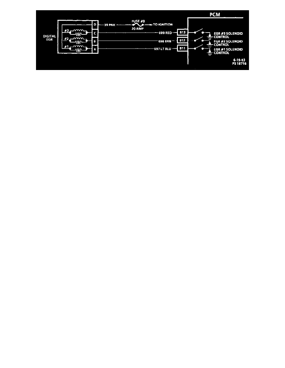
Digital EGR Solenoid Wiring Schematic
DIAGNOSIS
An Exhaust Gas Recirculation (EGR) flow check diagnosis of the digital EGR system is covered in CHART C-7 EGR System Check. Under
Computers and Control Systems/System Diagnosis/Procedures/Diagnostic Charts/A Charts. See: Computers and Control Systems/Testing
and Inspection/Diagnostic Trouble Code Tests and Associated Procedures/Related Tests and Information/C Charts/Chart C-7 EGR System Check
REMOVE OR DISCONNECT
1. Negative battery cable.
2. Electrical connector at solenoid.
3. Two base to pad bolt/screws.
4. Digital EGR valve.
INSTALL OR CONNECT
1. EGR valve gasket and visually align boles.
2. Align bolts through EGR valve assembly and cast EGR pad of the upper intake manifold and into pipe assembly and torque to 25 Nm (18 lb
ft).
3. Electrical connector at solenoid.
4. Negative battery cable.