
Beretta V6-3100 3.1L VIN M SFI (1995)
Ignition Control Module: Description and Operation
Electronic Ignition (EI) System With Ignition Control (IC)
PURPOSE
The Ignition Control Module (ICM) performs several functions:
^
It powers the 3X crankshaft sensor circuit.
^
It determines the correct ignition coil firing sequence, based on 3X pulse. This coil sequencing occurs at Start-up. After the engine is running,
the module determines the sequence, and continues triggering the ignition coils in proper sequence.
^
It sends a "3X crankshaft reference" (fuel control) signal to the PCM. The PCM determines engine RPM from this signal. It is also used by the
Powertrain Control module (PCM) to determine crankshaft position for ignition control spark advance calculations. The signal sent to the
PCM by the ICM is an "ON-OFF' pulse occurring 3 times per crankshaft revolution.
Operation
To properly control timing, the PCM relies on the following information:
^
Engine load (manifold pressure or vacuum).
^
Atmospheric (barometric) pressure.
^
Engine temperature.
^
intake air temperature.
^
Crankshaft position.
^
Engine speed (RPM).
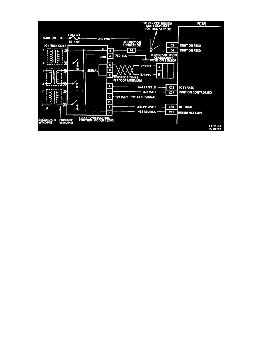
The Ignition Control (IC) system consists of the ignition coil and module assembly (ignition coils, electronic ICM), the 3X crankshaft position
sensor and the 24X crankshaft position sensor, PCM and connecting wires. The electronic ICM connector terminals are lettered as shown in
image. These circuits perform the following functions:
^
3X reference high - Circuit (CKT) 430. The crankshaft position sensor sends a signal to the electronic ignition control module which
generates a reference pulse which is sent to the PCM. The PCM uses this signal to calculate crankshaft position and engine speed (also
used to trigger the injector).