
Beretta V6-3100 3.1L VIN M SFI (1995)
Throttle Position Sensor: Description and Operation
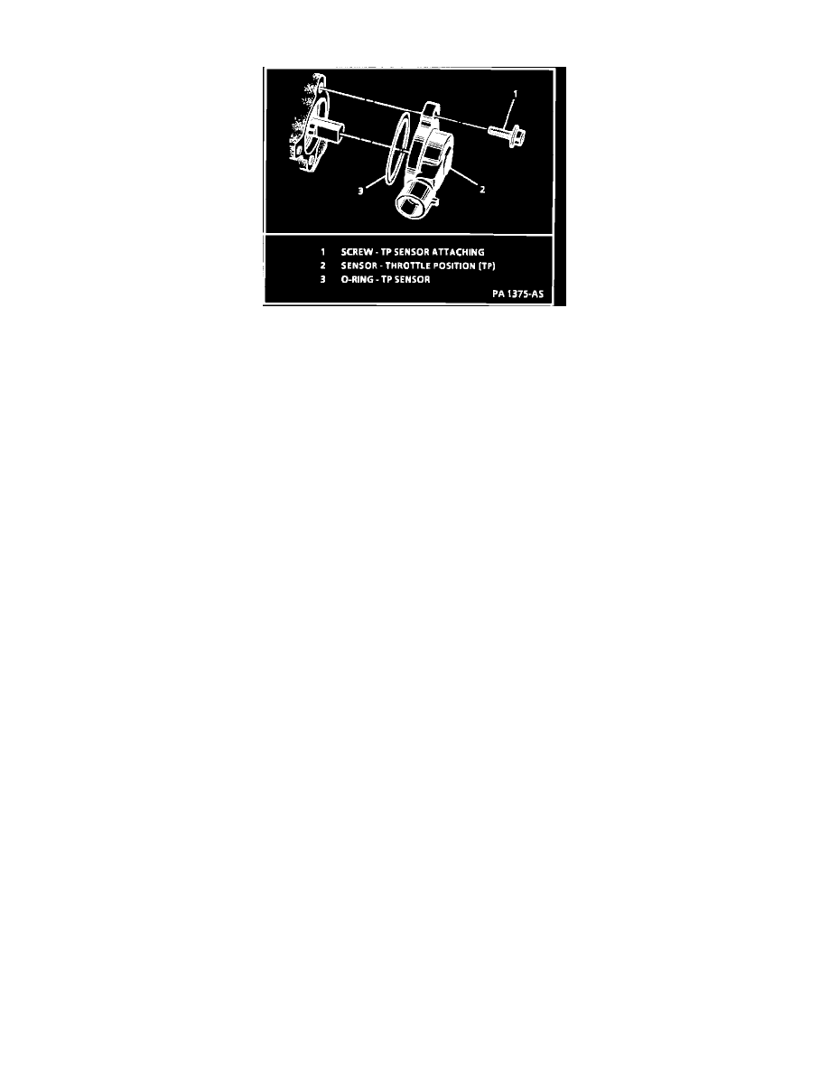
Throttle Position Sensor Installation
PURPOSE
The Throttle Position (TP) sensor is a potentiometer connected to the throttle shaft on the throttle body. The TP sensor electrical circuit consists of
a 5.0 volts supply line and a ground line, both provided by the Powertrain Control Module (PCM). By monitoring the voltage on this signal line
the PCM calculates throttle position.
OPERATI0N
As the throttle valve angle is changed (accelerator pedal moved), the output of the TP sensor also changes. At a closed throttle position, the output
of the TP sensor is low (approximately 0.29 to 0.98 volt). As the throttle valve opens, the output increases so that, at wide-open throttle, the output
voltage should be approximately 5.0 volts.
The PCM can determine fuel delivery based on throttle valve angle (driver demand). A broken or loose TP sensor can cause intermittent bursts of
fuel from the injectors and an unstable idle because the PCM thinks the throttle is moving. A problem in any of the TP sensor circuits should set
either a DTC 21 or 22. Once a diagnostic trouble code is set, the PCM will use an artificial default value for TP sensor and some vehicle
performance will return. A high idle will result when either DTC 21 or DTC 22 is set.