
Blazer 4WD V6-4.3L VIN X (2005)
Removal Procedure
Important: Observe and mark the positions of all the driveline components relative to the propeller shaft and the axles prior to disassembly. These
components include the propeller shafts, drive axles, pinion flanges, output shafts, etc. Assemble all the components in the exact places in which you
removed the parts. Follow any specifications, torque values, and measurements obtained prior to disassembly.
1. Raise the vehicle. Refer to Vehicle Lifting.
2. Remove the tire and wheel assemblies.
3. Remove the rear brake calipers.
4. Remove the brake rotors.
5. Disconnect the propeller shaft from the drive pinion yoke.
Position and secure the propeller shaft away from the rear axle.
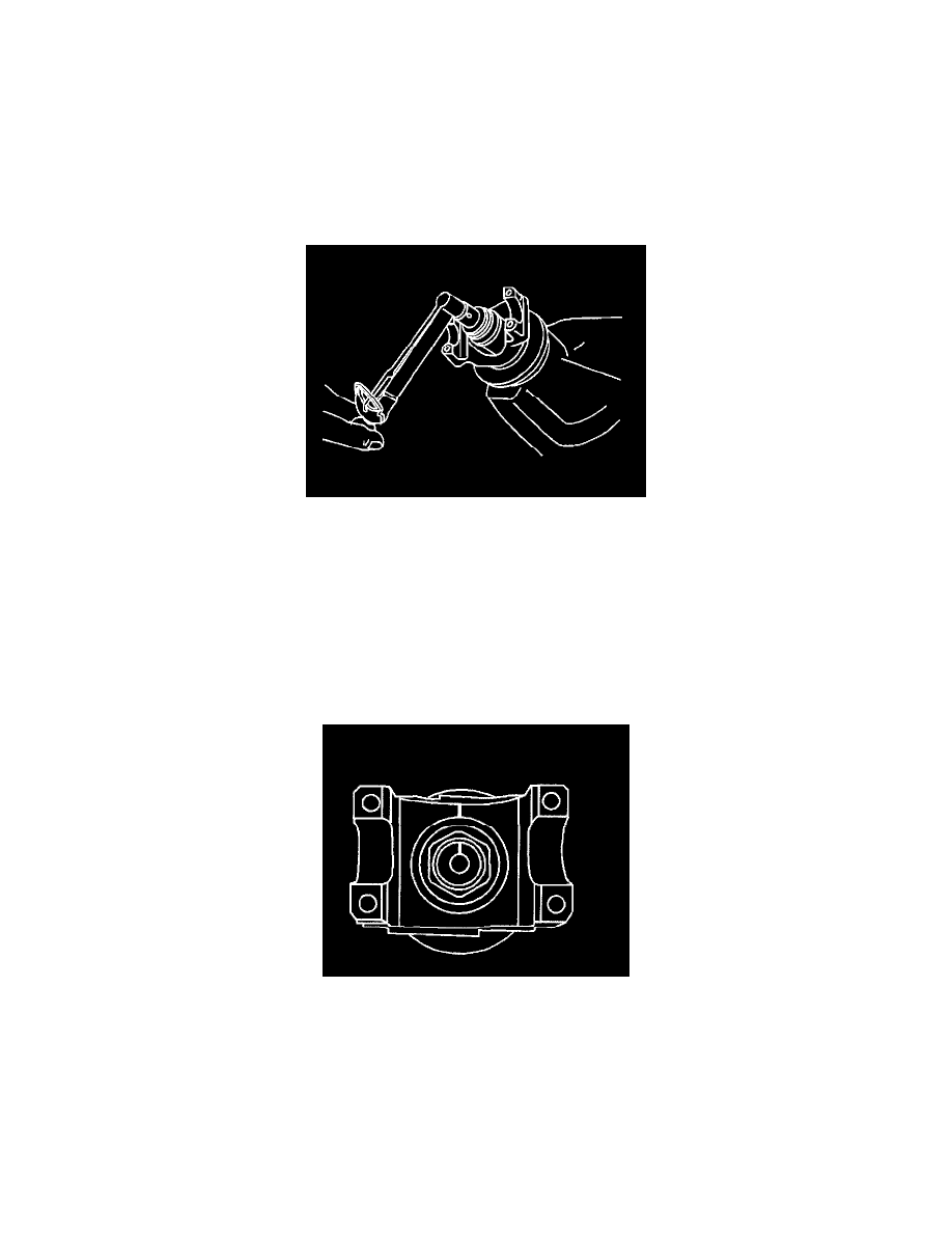
6. Measure the amount of torque required to rotate the pinion using an inch-pound torque wrench. This will give the combined preload for the
following components:
^
The pinion bearings
^
The pinion seal
^
The carrier bearings
^
The axle bearings
^
The axle seals
7. Record the measurement.
8. Draw an alignment mark between the pinion stem and the pinion flange/yoke.