
C 10 P/U 2WD V6-262 4.3L (1985)
^
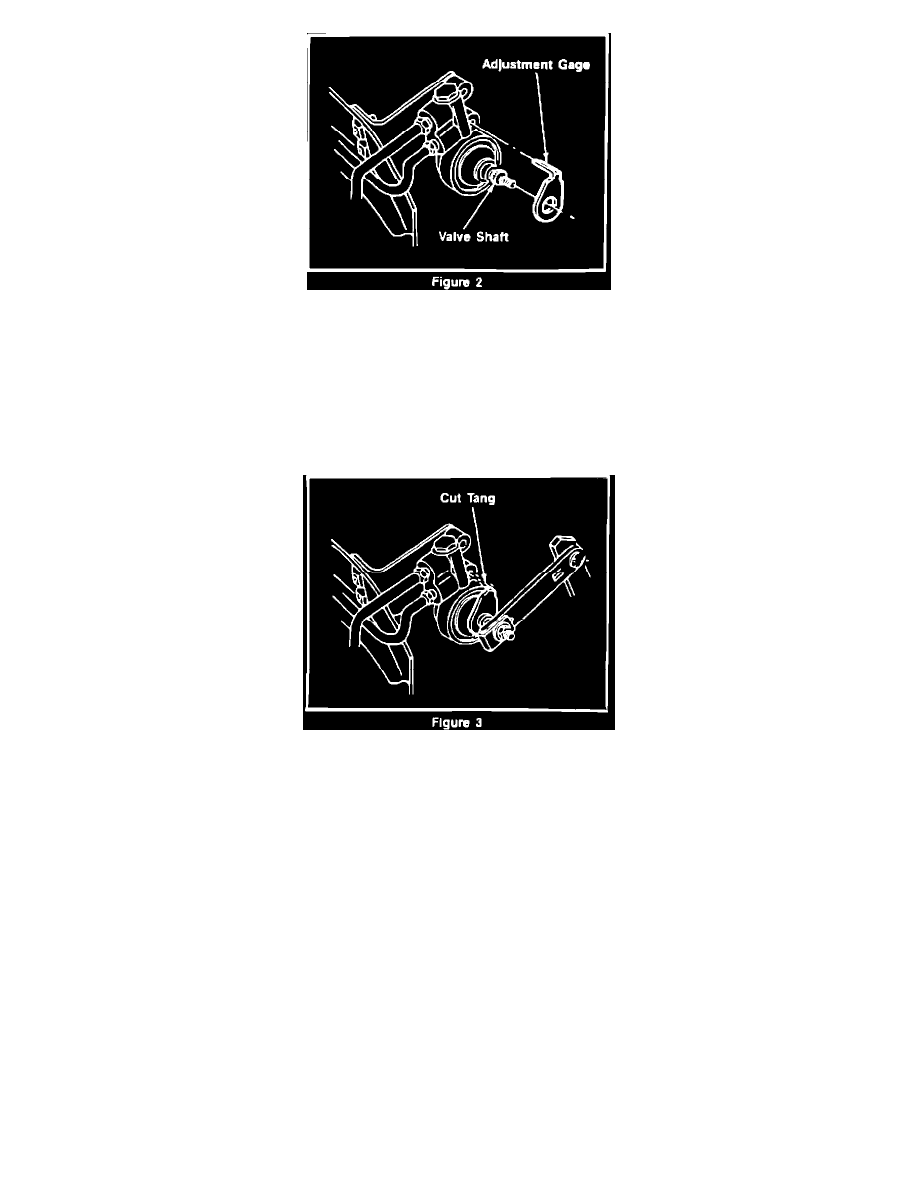
Rotate valve shaft to permit installation of plastic adjustment gage. Center "D" shaped hole of gage must seat over "D" shape of the valve
shaft and gage tang must be positioned in valve mounting hole (Figure 2).
^
Reinstall lever assembly to the valve shaft utilizing a "C" clamp or channel lock pliers to seat lever nylon bushing to serration on the valve
shaft.
Important:
Do not drive the lever onto the shaft using the attaching nut. Doing so may result in improper valve setting.
^
Reinstall valve shaft nut and torque to 8 - 11 N-m (70 - 98 lbs.in.)
^
Cut gage tang from body of the adjustment gage to allow the valve assembly to rotate freely (Figure 3).
^
Lower vehicle and test brakes.
SERVICE PARTS INFORMATION
Model
P/N
Description
Code
Color
C2,R20906
14061394
Gage
A
Green
K2,V20906
15548904
Gage
E
Yellow
BRAKE BURNISHING
^
On dry clean level roadway, accelerate to 55 mph., observe traffic following and when its clear
^
Apply brake at a deceleration rate of 8 ft/sec/sec until vehicle speed is 25 mph. A decelerometer must be used to achieve the proper
deceleration rate.
^
Repeat this procedure at 1 mile intervals 15 times.
Decelerometers are available from various sources, one of which is:
Ammco Tool Company