
C 1500 Suburban 2WD V8-4.8L VIN V (2002)
11.
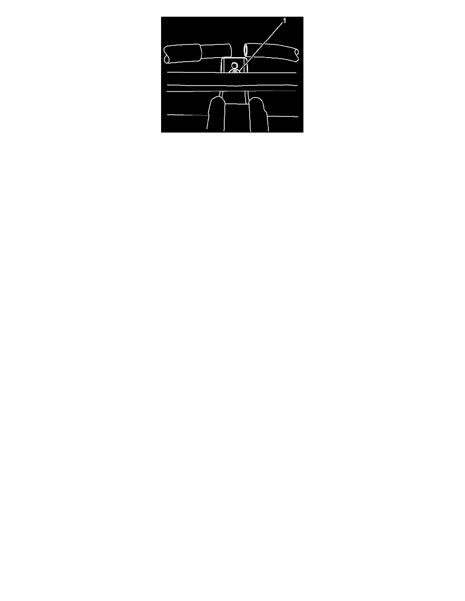
From under the vehicle, mark the location on the auxiliary evaporator line where the line will be cut. Using the forward running board bracket as a
reference, mark the location inline with the bracket-to-body bolt (1). If the vehicle is not equipped with running boards, mark the location inline
with the bolt hole.
12.
Using a tubing cutter, cut the marked section of the auxiliary evaporator line.
13.
Remove the front section of the auxiliary evaporator hose from the vehicle and discard.
14.
Install the new front section of the auxiliary evaporator hose into the vehicle.
15.
On both sections of the auxiliary evaporator line, cut back the plastic coating approximately 76 mm (3 in).
16.
Splice in the new front section of the auxiliary evaporator hose using J 41425 A/C Line Repair Kit and J 41425-750 splice. Refer to the Heater and
A/C Pipe Repair-Auxiliary procedure in the Service Manual.
17.
Install the auxiliary evaporator hose to the accumulator line block and nut.
Tighten
Tighten the nut to 16 N.m (12 lb ft).
18.
Secure the line retaining clamps.
19.
Install the wheelhouse panel.
20.
Install the wheel assembly.
21.
Lower the vehicle.
22.
Inject the oil into the A/C system that was removed during the recovery process using J 45037 A/C Oil Injection Kit.
23.
Evacuate and recharge the refrigerant. Refer to Refrigerant Recovery and Recharging in the HVAC sub-section of the Service Manual.
24.
Leak test the fitting and splice using J 39400-A Halogen Leak Detector.
25.
Replace the right front shock absorber solenoid connector using service connector, P/N 88986417. Refer to Wiring Repairs in the Wiring Systems
sub-section of the Service Manual.