
C 1500 Suburban 2WD V8-6.5L DSL Turbo VIN F (1997)
Alternator: Description and Operation
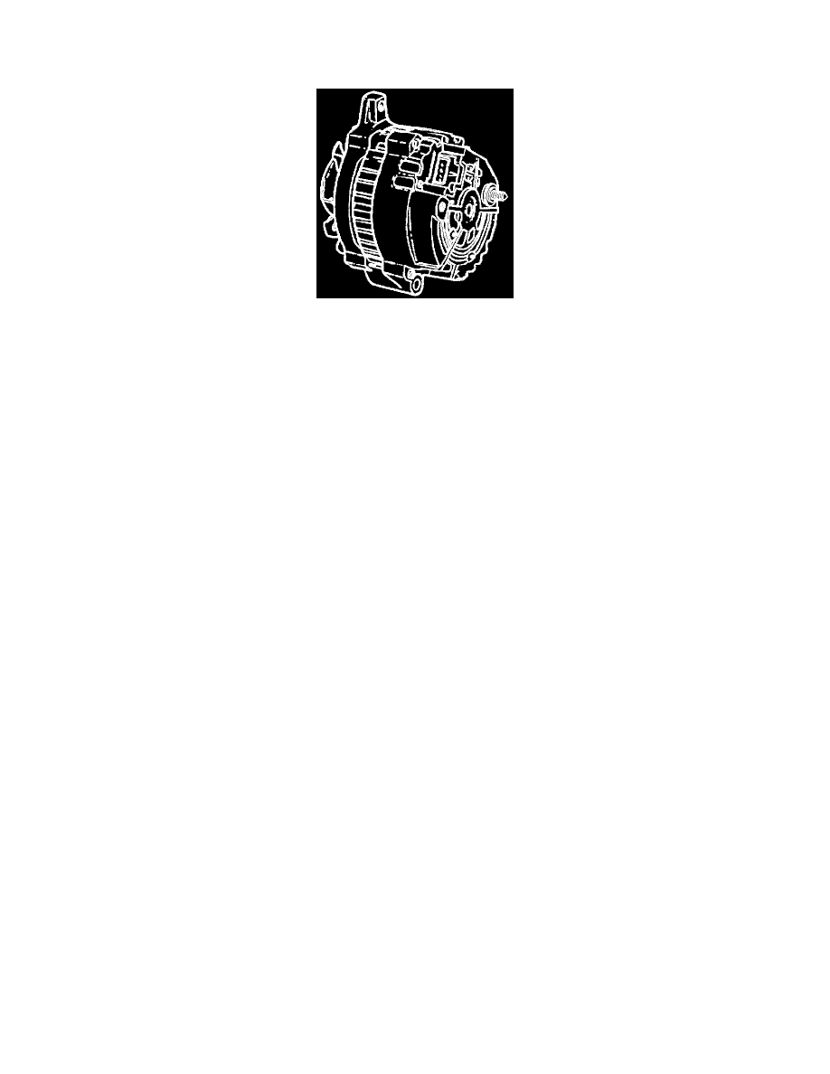
CS-130 Generator
CS-130 Generator
The CS-130 generator features a high ampere output per pound of weight. CS stands for Charging System and 130 is the measurement in millimeters of
the outside diameter of the stator laminations.
This generator with integral regulator does not have a diode trio. The delta stator, rectifier bridge, and rotor with slip rings and brushes are electrically
similar to those in other CS-series generators. A conventional fan and pulley is used and an internal fan cools the slip rings, end frame, rectifier bridge,
and regulator.
The charging system indicator, that appears on the instrument panel as a battery symbol, turns on when the ignition switch is closed and turns off when
the engine is running. If the charging system indicator is on with the engine running, a charging system problem is indicated. This indicator will glow at
full brilliance, not half lit, if any charging problem occurs or the system voltage is too high or low.
The regulator voltage setting varies with temperature and limits system voltage by controlling rotor field current. When the field current is "ON," the
regulator actually switches the rotor field current on and off at a fixed rate of about 400 cycles per second. By varying the overall on-off time, correct
average field current for proper system voltage control is obtained. At high speeds, the on-time may be 10 percent and the off-time 90 percent. At low
speeds, with high electrical loads, on-off time may be 90 percent and 10 percent respectively.
The regulator has four terminals: "P," "L," "I," and "S.,, The regulator and/or the connector may be stamped "PLI/FS," or "PLFS."
Either the "L" or "I" terminal (or both) turns the regulator on and allows field current to flow when the switch is closed. The "L" terminal must be
connected through an indicator lamp or a suitable resistor. The "I" terminal may be connected either directly to battery positive or through a resistor.
These two terminals are often used in parallel, connected to two different vehicle circuits. The "P" terminal is connected internally to the stator and may
be wired to a tachometer or other device. The "S" terminal may be used to sense voltage at another location on the vehicle for voltage control. If the "S"
terminal is not used, the generator uses an internal voltage sense for control.
The generator is not serviceable and no periodic maintenance is required. It should not be disassembled for any reason.