
C 1500 Truck 2WD V6-4.3L VIN X (2003)
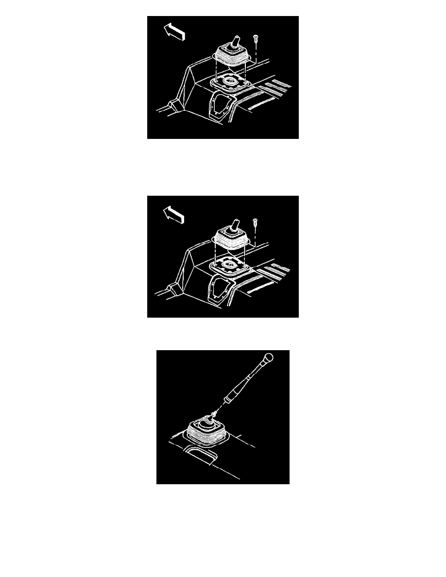
4. Remove the control lever boot screws, if necessary.
5. Remove the control lever boot, if necessary.
6. Remove the control lever insulator, if necessary.
Installation Procedure
1. Install the control lever insulator, if removed
2. Install the control lever boot to the control lever, if removed.
3. Install the control lever.
4. If alignment of the control lever is necessary, or if the shift lever assembly was replaced perform the following:
4.1.
The nut must be seated at the bettors of the thread runout on the shift lever
4.2.
Seat the control lever against the shift lever assembly adjustment nut.
4.3.
Back the control lever off the nut its order to align the index mark on the control lever perpendicular to the edge of the control lever boot
retainer.
5. Ensure that the index mark is located on the passenger side and that the shift pattern IS aligned parallel to the vehicle centerline a, rotated no more
than 6 degrees clockwise.