
C 1500 Truck 2WD V8-350 5.7L VIN K TBI (1995)
MAP Sensor Circuit
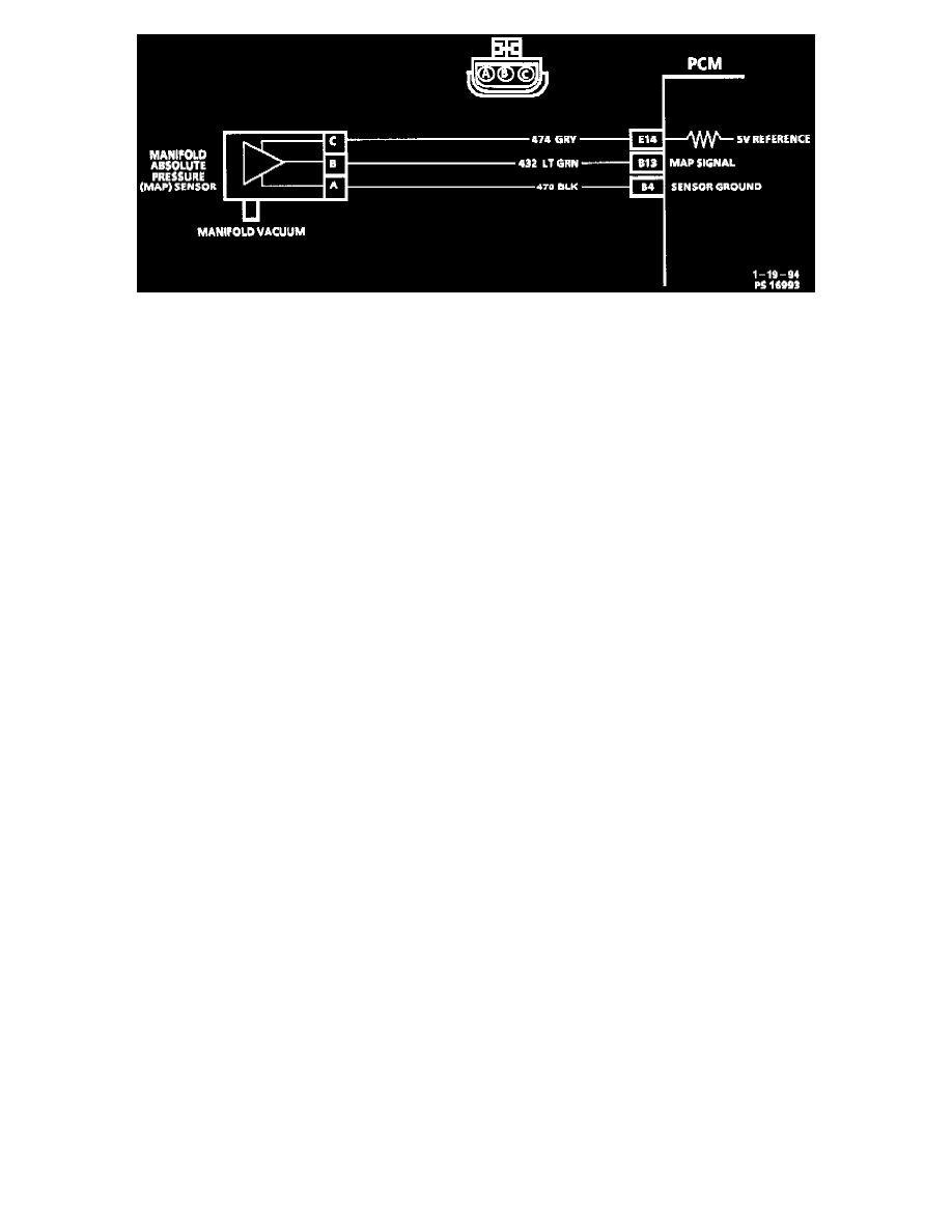
CIRCUIT DESCRIPTION
The Manifold Absolute Pressure (MAP) sensor measures the changes in the intake manifold pressure which result from engine load (intake
manifold vacuum) and rpm changes; and converts these into a voltage output. The PCM sends a 5 volt reference voltage to the MAP sensor. As the
manifold pressure changes, the output voltage of the sensor also changes. By monitoring the sensor output voltage, the PCM knows the manifold
pressure. At lower pressure output voltage will be about 1 to 2 volts at idle. While at higher pressure or at Wide Open Throttle (WOT) output
voltage will be about 4 to 4.8 volts. The MAP sensor is also used, under certain conditions, to measure barometric pressure, allowing the PCM to
make adjustments for different altitudes. The PCM uses the MAP sensor to control fuel delivery and ignition timing.
CHART TEST DESCRIPTION
Number(s) below refer to circled number(s) on the diagnostic chart.
IMPORTANT: Be sure to use the same diagnostic test equipment for all measurements.
1. Checks MAP sensor output voltage to the PCM. This voltage, without engine running, represents a barometer reading to the PCM.
^
When comparing Tech 1 scan readings to a known good vehicle, it is important to compare vehicles that use a MAP sensor having the same
color insert or having the same "Hot Stamped" number. Refer to figures in chart.
2. Applying 34 kPa (10" Hg) vacuum to the MAP sensor should cause the voltage to change. Subtract second reading from the first. Voltage value
should be greater than 1.5 volts. Upon applying vacuum to the sensor, the change in voltage should be instantaneous. A slow voltage change
indicates a faulty sensor.
3. Check vacuum hose to sensor for leaking or restriction. Be sure that no other vacuum devices are connected to the MAP hose.
NOTE: Make sure electrical connector remains securely fastened.
4. Disconnect sensor from bracket and twist sensor by hand (only) to check for intermittent connection. Output changes greater than 0.1 volt indicate
a bad connector or connection. If OK, replace sensor.