
C 1500 Truck 2WD V8-393 6.5L DSL Turbo VIN S (1996)
12.
Install the case onto an axle shaft supported in a vise.
13.
Insert a screwdriver between the pinion shaft and the face of the side gear. Force the screwdriver in until the clutch pack is compressed.
14.
Check the backlash between the side gear and pinion gears. If backlash does not fall into the range of .005 inch to .008 inch, adjust the shim
dimension as required. Increasing shim thickness will decrease backlash; decreasing shim thickness will increase backlash. Service shims are
available from .070 inch to .122 inch in increments of .004 inch.
15.
Remove the pinion shaft, pinion gears, side gear, clutch pack and shim from the case.
16.
Install the opposite gear, clutch pack and original shim into the opposite side of the case. Place both pinion gears and thrust washers into place,
and install the pinion shaft.
17.
Follow the procedure in steps 12, 13, and 14 to determine the proper shim dimension.
18.
When proper shim dimensions have been determined, remove pinion gears and pinion shaft and install both side gears, shims and clutch packs into
case.
19.
Mount the case onto the axle shaft locked in a vise. Place both pinions and thrust washers into position 180° apart and carefully ``roll in'' by
turning the case on the shaft. A large ``C'' clamp may be used to apply slight compression against pinion gears to aid the ``rolling in'' procedure.
20.
Tap the preload spring into place with a hammer.
21.
Install the pinion shaft and lock screw.
22.
Install the side bearings and ring gear using the procedure outlined for conventional units.
23.
Place the differential unit in the carrier and adjust ring gear and pinion backlash, and gear tooth pattern.
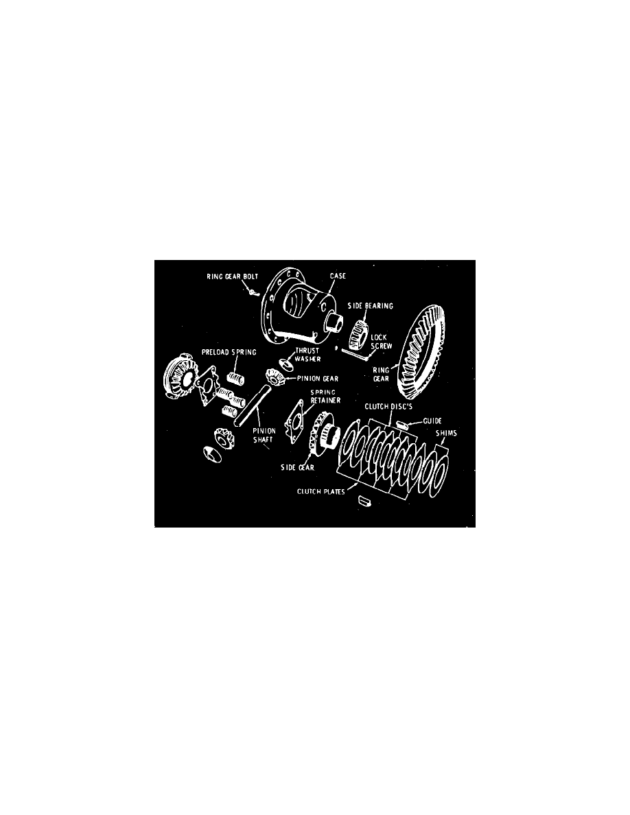
Limited Slip
Fig. 6 Eaton limited slip differential exploded view
1.
Remove pinion shaft lock screw and pull pinion shaft from case,
Fig. 6.
2.
Remove preload spring retainer and springs.
3.
Rotate side gears until pinions are in open area of case and pick out pinions and thrust washers.
4.
Remove a side gear, clutch pack and shims, noting shim location in case to aid in reassembly. Remove side gear clutch pack and shims from
opposite side. If side gear or clutch pack cannot be removed readily, drive it out with a brass drift.
5.
Remove clutch plate guides and separate shims and clutch plates from side gears.
Keep clutch plates in their original location in clutch pack.
6.
If pinion shaft, pinions or side gears are excessively scored, pitted or worn, replace parts affected.
7.
Inspect clutch plates for scored, worn, cracked or distorted condition. If any of these conditions exist, new clutch plates must be installed.
8.
Alternately position nine clutch plates on side gear, starting and ending with a plate with external lugs,
Fig. 6.
9.
Install two clutch guides over clutch plate lugs.
10.
Install same shims which were removed or an equal amount on clutch plate.
11.
Repeat above steps on other clutch pack.
12.
Install one side gear with clutch pack and shims in case.
13.
Position two pinion gears and thrust washers on side gear and install pinion shaft.
14.
Compress clutch pack by inserting a screwdriver or wedge between side gear and pinion shaft.
15.
Install a suitable dial indicator with contact button against pinion gear.
16.
Rotate pinion gear. Clearance should be .001 inch to .006 inch.
17.
If clearance is more than .006 inch, add shims between clutch pack and case. If clearance is less than .001 inch, remove shims. A .002 inch shim
will change clearance about .001 inch. Recheck clearance after adding or subtracting shims.