
C 1500 Truck 2WD V8-4.8L VIN V (2001)
18. Disconnect the inflatable restraint IP module connector (1) located behind the main IP support. Access the connector by opening the glove box and
pressing in on the sides. This will allow the glove box to extend beyond the stops and to fully open. The IP module connector will be attached to
the main IP support.
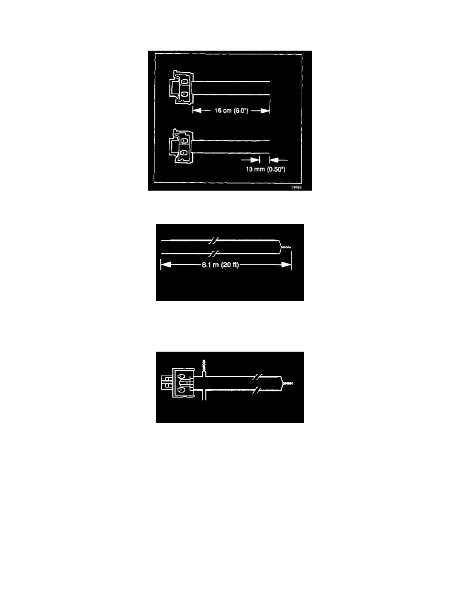
19. Cut the LF side impact module harness connector out of the vehicle leaving at least 16 cm (6 in) of wire at the connector.
20. Strip 13 mm (0.5 in) of insulation from each of the LF side impact module connector wire leads.
21. Cut 26.1 m (20 ft) deployment wires from a 0.8 mm (18 gage) or thicker multi-strand wire. Use these wires to fabricate the deployment harness.
22. Strip 13 mm (0.5 in) of insulation from both ends of the wires cut in the previous step.
23. Twist together 1 end from each of the wires in order to short the wires. Deployment wires shall remain shorted, and not connected to a power
source until you are ready to deploy the side impact module.
24. Twist together 1 connector wire lead to 1 deployment wire.