
C 1500 Truck 2WD V8-6.5L DSL Turbo VIN F (1998)
Steering Wheel Speed Sensor: Service and Repair
Steering Wheel Position Sensor or Steering Shaft Lower Bearing Replacement (Centering Not Required)
Tools Required
J 42640 Steering Column Anti Rotation Pin
Removal Procedure
1. Set the front wheels in the straight-ahead position.
2. Install J 42640 or set the steering wheel in the LOCKED position.
Caution: Unless directed otherwise, the ignition and start switch must be in the OFF or LOCK position, and all electrical loads must be OFF before
servicing any electrical component. Disconnect the negative battery cable to prevent an electrical spark should a tool or equipment come in
contact with an exposed electrical terminal. Failure to follow these precautions may result in personal injury and/or damage to the vehicle
or its components.
For Vehicles equipped with OnStar® (UE1) with Back Up Battery:
The Back Up Battery is a redundant power supply to allow limited OnStar® functionality in the event of a main vehicle battery power
disruption to the VCIM (OnStar®module). Do not disconnect the main vehicle battery or remove the OnStar® fuse with the ignition key in
any position other than OFF. Retained accessory power (RAP) should be allowed to time out or be disabled (simply opening the driver
door should disable RAP) before disconnecting power. Disconnecting power to the OnStar® module in any way while the ignition is On or
with RAP activated may cause activation of the OnStar® Back-Up Battery (BUB) system and will discharge and permanently damage the
back-up battery. Once the Back-Up Battery is activated it will stay on until it has completely discharged. The BUB is not rechargeable and
once activated the BUB must be replaced.
3. Disconnect the negative battery cable.
4. Disable the supplemental inflatable restraint (SIR). See: Steering/Steering Column/Air Bag(s) Arming and Disarming/Service and Repair
Important: You MUST make an alignment mark on the upper to lower steering shaft connection. You will need the alignment marks for installation.
5. Make an alignment mark on the upper and lower steering shafts where they connect before removal.
6. Remove the nut and the bolt from the upper to the lower steering shaft connection.
-
Slide the lower shaft down.
7. Remove the steering wheel position sensor connector by using a suitable tool in order to pull the connector down around the right side of the
steering column for accessibility.
Important: Remove the steering wheel position sensor connector by using a suitable tool in order to pull the connector down around the right side of
the steering column for accessibility.
-
The steering wheel position sensor does NOT require centering.
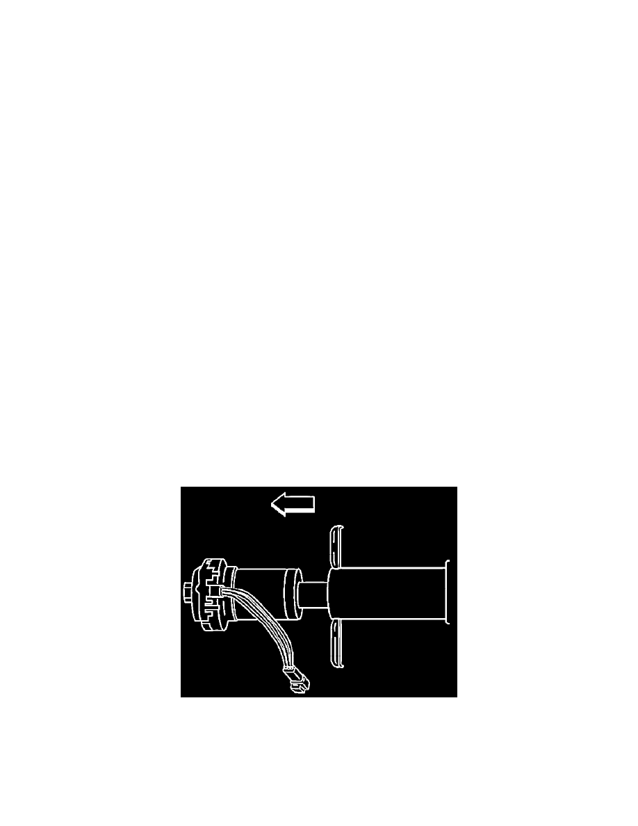
8. Remove the steering wheel position sensor and adapter and bearing assembly from the steering column jacket by pulling the assembly straight out.
9. Remove the steering wheel position sensor from the clips in the adapter and bearing assembly.