
C 2500 Suburban 2WD V8-454 7.4L VIN J SFI (1998)
2. Relieve the fuel system pressure. Refer to the Fuel Pressure Release Procedure.
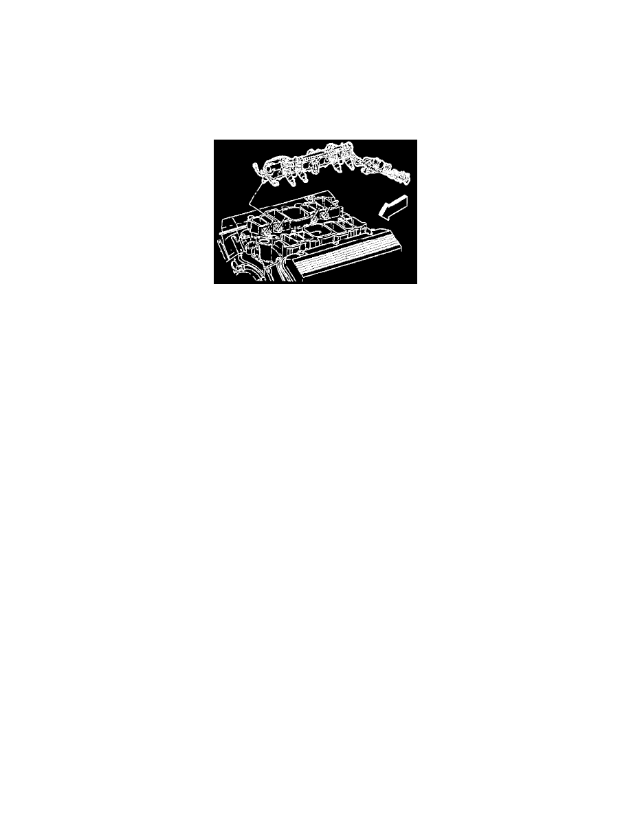
3. Remove the intake manifold plenum. Refer to Engine Mechanical.
4. Remove the high voltage switch assembly.
5. Disconnect the engine fuel pipes at the rail.
6. Remove the engine fuel pipe bracket bolt.
7. Remove the fuel inlet and return line O-rings and discard.
8. Disconnect the injector electrical connectors and remove from the coil bracket.
9. Remove the fuel rail retaining bolts (5).
10. Disconnect the vacuum hose line to pressure regulator.
Diagram
11. Remove the fuel rail from the intake manifold.
12. Remove the injector O-ring seal from the spray tip end of each injector. Discard the seals. With the O-ring removed, the O-ring backup may slip
off of the injector. Be sure to retain O-ring backup for reuse.
INSTALLATION PROCEDURE
IMPORTANT: Ensure that the O-ring backups are on the injectors before installing the new O-rings. Lubricate the new injector O-ring seals with
clean engine oil and install on the spray tip end of each injector.
1. Install the fuel rail assembly in intake manifold. tilt the rail assembly to install the injectors.
2. Install the fuel rail attaching bolts. Tighten tighten the fuel rail attaching bolts to 10 Nm (89 lb. in.).
3. Connect the injector electrical connectors.
4. Install the new O-rings on the fuel pipes.
5. Connect the fuel feed and return lines. Tighten
-
Engine fuel pipe nuts to 27 Nm (20 lb. ft.).
-
Use a back-up wrench on the fittings to prevent them from turning.
6. Connect the negative battery cable.
7. Install the fuel filler cap.
8. Check for fuel leaks.
8.1. Turn the ignition switch to the ON position for 2 seconds.
8.2. Turn the ignition switch to the OFF position for 10 seconds.
8.3. Again, turn the ignition switch to the ON position.
8.4. Check for fuel leaks.
9. Install the intake manifold plenum. Refer to Engine Mechanical.
Steel Fuel Line Repair
IMPORTANT NOTES
-
Steel fuel lines - These are welded steel tubes, meeting GM specifications 124-M, or its equivalent. The fuel feed line is 3/8 inches diameter and
the fuel return line is 5/16 inches diameter. Do not use copper or aluminum tubing to replace steel tubing. Those materials do not have satisfactory
durability to withstand normal vehicle vibration.
-
Coupled hose - Do not repair the hoses. Replace them only as an assembly.
-
Uncoupled hose - Use only reinforced fuel resistant hose, made of Fluoroelastomer material. Do not use a hose within 4 inches (100 mm) of any
part of the exhaust system, or within 10 inches (2154 mm) of the catalytic converter. The hoses inside diameter must match the outside diameter of
the steel tubing.
-
Clamps - These are stainless steel, screw bank-type clamps, #2494772, or equivalent.
PROCEDURE
1. Cut a piece of fuel hose 4 inches (100 mm) longer than the section of line to be removed. If you remove more than 6 inches (152 mm), use a
combination of steel pipe and hose. The hose length should not be more than 10 inches total.