C 2500 Suburban 2WD V8-6.5L DSL Turbo VIN F (1995)

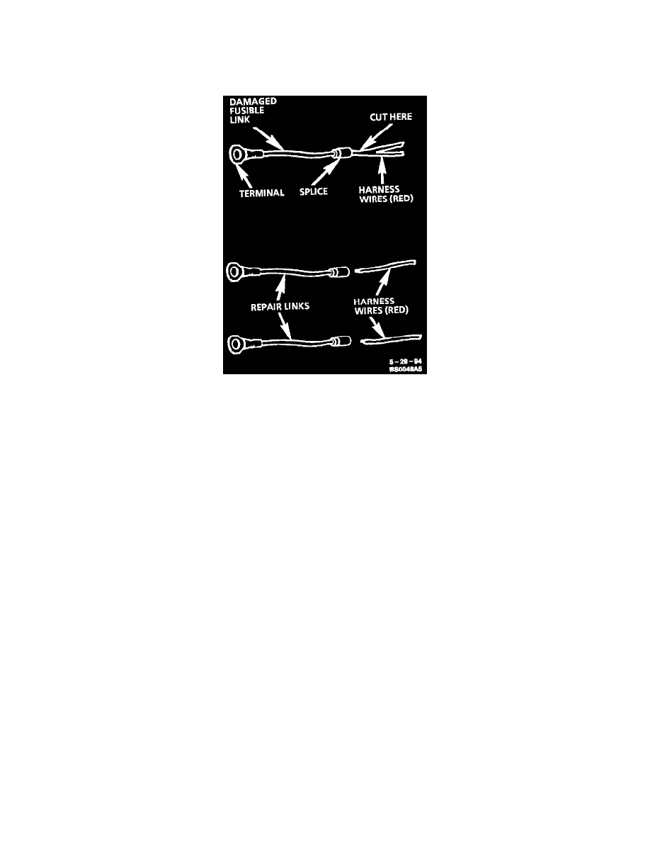
Single Wire Feed Fusible Link
To replace a damaged fusible link, cut it off beyond the splice. Replace with a repair link. When connecting the repair link, strip wire and use
staking-type pliers to crimp the splice securely in two places. For more details on splicing procedures, refer to "Typical Electrical Repair Procedures."
Use crimp and seal splices whenever possible. See: Wire Repair Procedures/Typical Electrical Repair Procedures
Double Wire Feed Fusible Link
To replace a damaged fusible link which feeds two harness wires, cut them both off beyond the splice. Use two repair links, one spliced to each harness
wire.
Additional Information
NOTE: Turn OFF power to the test circuit before attempting in-circuit resistance measurements to prevent false readings or damage to the meter. Do
not use the meter to measure resistance through a solid state module.
Continuity tests that work well for detecting intermittent shorts to ground can be performed by setting the meter to "ohms" then pressing the "PEAK
MIN MAX" button. An audible tone will be heard whenever the meter detects continuity for at least 1 millisecond.
The J 39200 Instruction Manual is a good source of information and should be read thoroughly upon receipt of the meter as well as kept on hand for
reference during new procedures.
Basic Knowledge Required
Without a basic knowledge of electricity, it will be difficult to use the diagnostic procedures contained in this section. You should understand the basic
theory of electricity and know the meaning of voltage, current (amps) and resistance (ohms). You should understand what happens in a circuit with an
open or a shorted wire. You should be able to read and understand a wiring diagram.
The following four-step troubleshooting procedure is recommended:
Step 1: Check the Problem
Perform a System Check to determine a symptom. Don't waste time fixing part of the problem! Do not begin disassembly or testing until you have
narrowed down the possible causes.
Step 2: Read the Electrical Schematic
Study the schematic. Read the Circuit Operation text if you do not understand how the circuit should work. Check circuits that share wiring with
the problem circuit. (Shared circuits are shown on Power Distribution, Ground Distribution, Fuse Block Details and Light Switch Details.) Try to
operate the shared circuits. If the shared circuits work, then the shared wiring is OK. The cause must be within the wiring used only by the problem
circuit. If several circuits fail at the same time, chances are the power (fuse) or ground circuit is faulty.
Step 3: Find the fault and repair
^
Narrow down the possible causes.
^
Use the Troubleshooting Hints.
^
Make the necessary measurements or checks as given in the System Diagnosis.
