
C 2500 Suburban 2WD V8-6.5L DSL Turbo VIN F (1995)
Step 2: Cut the Wire
Begin by cutting as little wire off the harness as possible. You may need the extra length of wire later if you decide to cut more wire to change the
location of a splice. You may have to adjust splice locations to make certain that each splice is at least 40 mm (1.5 in.) away from other splices,
harness branches or connectors. This will help prevent moisture from bridging adjacent splices and causing damage.
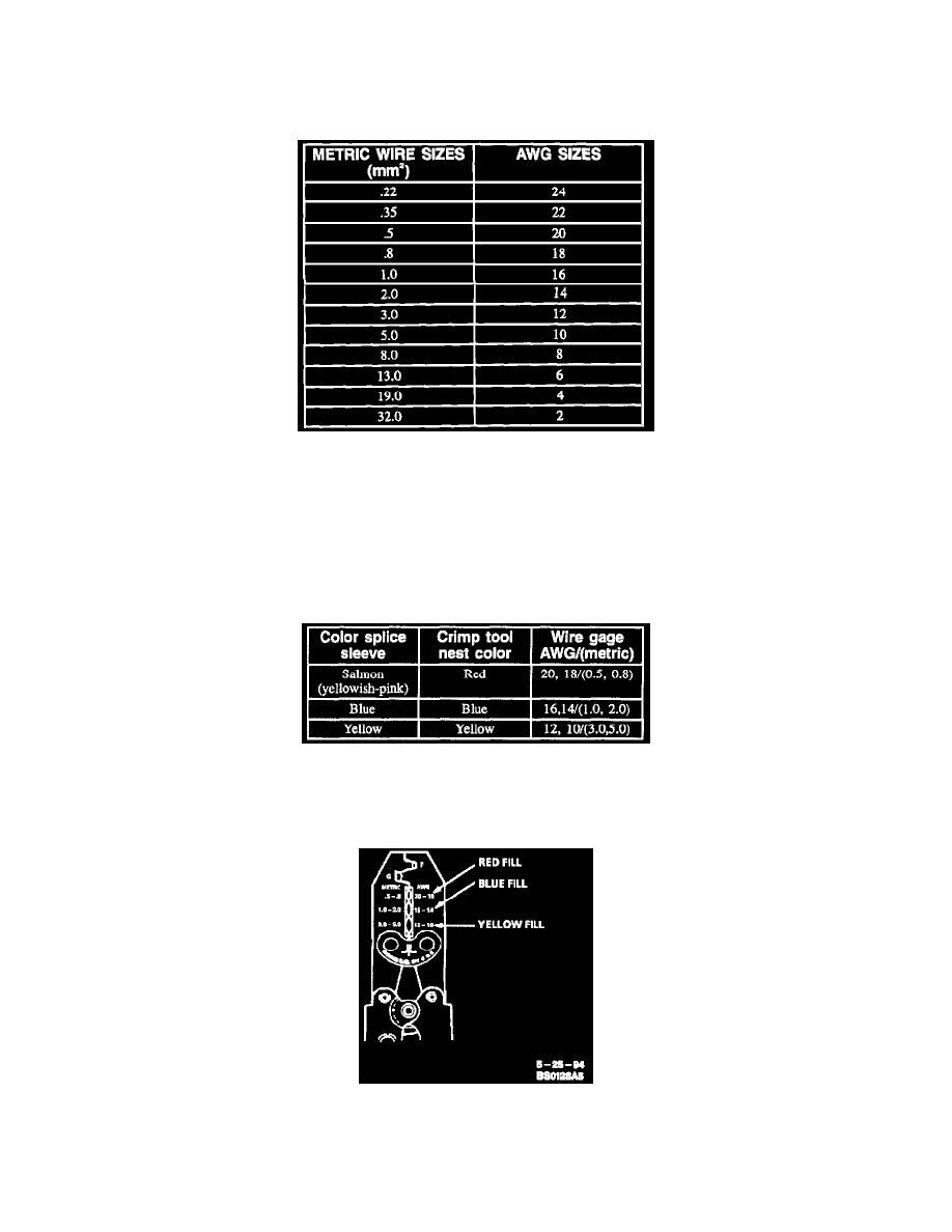
Wire Size Conversion Table
Step 3: Strip the Insulation
If it is necessary to add a length of wire to the existing harness, be certain to use the same size as the original wire.
To find the correct wire size either find the wire on the schematic and convert the metric size to the equivalent AWG size or use an AWG wire
gage. If unsure about the wire size, begin with the largest opening in the wire stripper and work down until a clean strip of the insulation is
removed. Strip approximately 7.5 mm (5/16 in.) of insulation from each wire to be spliced. Be careful to avoid nicking or cutting any of the wires.
Check the stripped wire for nicks or cut strands. If the wire is damaged, repeat this procedure after removing the damaged section.
Crimp And Seal Splice Sleeve Chart
Step 4: Select and Position the Splice Sleeve
Select the proper splice sleeve according to wire size. The splice sleeves and tool tests are color coded (refer to Chart).
Hand Crimp Tool
Using the J 38125-8 splice crimp tool, position the splice sleeve in the proper color nest of the hand crimp tool. Place the splice sleeve in the nest
so that the crimp falls midway between the end of the barrel and the stop.