
C 2500 Suburban 2WD V8-6.5L DSL Turbo VIN F (1995)
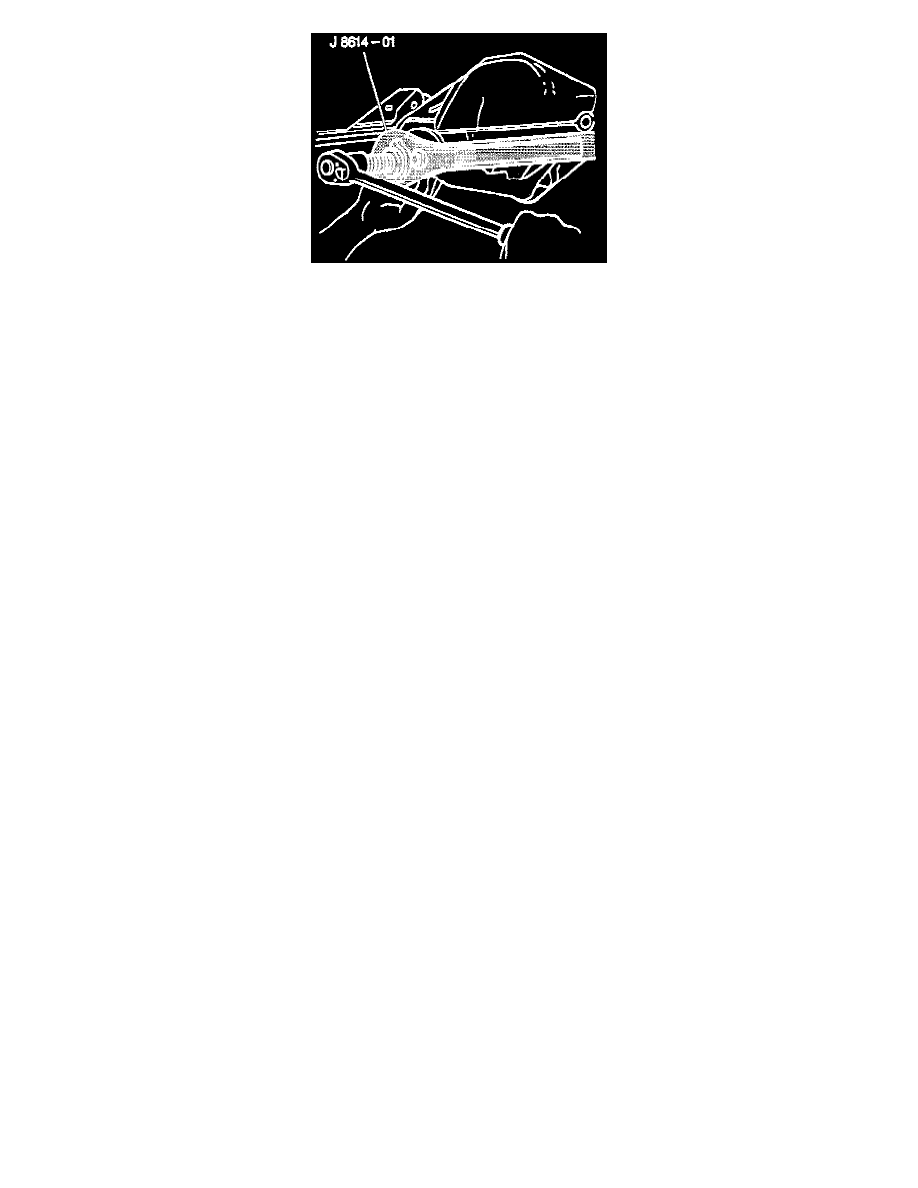
4. Pinion flange using J 8614-01.
-
Use container to catch lubricant.
5. Oil seal.
-
Pry the oil seal from the bore. Do not damage the machined surfaces. Thoroughly clean foreign material from the contact area.
-
Replace parts as necessary.
INSTALL OR CONNECT
NOTICE: Always use the correct fastener in the proper location. When you replace a fastener, use ONLY the exact part number for that application.
The manufacturer will call out those fasteners that require a replacement after removal. The manufacturer will also call out the fasteners that require
thread lockers or thread sealant. UNLESS OTHERWISE SPECIFIED, do not use supplemental coatings (paints, greases, or other corrosion inhibitors
on threaded fasteners or fastener joint interfaces. Generally, such coatings adversely affect the fastener torque and joint clamping force, and may
damage the fastener. When you Install fasteners, use the correct tightening sequence and specifications. Following these instructions can help you
avoid damage to parts and systems.
1. Oil seal into the bore using J 24384.
-
Lubricate the cavity between the new seal lips with a high melting point bearing lubricant.
2. Pinion flange.
-
Use scribed marks for installation.
Important: Do not attempt to hammer the pinion flange onto the pinion stem.
3. Washer and a new nut.
-
Tighten:
A. The nut on the pinion stem as close to the original marks as possible without going past the mark. Use the reference mark and the thread
count as reference.
B. The nut a little at a time and turn the pinion flange several times after each tightening to set the rollers.
Measure
-
Using an inch-pound torque wrench, the torque required to rotate the pinion. Compare this with the required rotating torque recorded earlier.
Continue tightening and measuring a little at a time until the same preload is achieved.
Important:
-
If the original preload torque value was less than 3 (inch lbs.) then reset the torque specification to 3-5 (inch lbs.).
-
Align the propeller shaft with the alignment marks made previously.
4. Propeller shaft.
5. Retainers and bolts.
-
Tighten bolts to 20 Nm (15 ft. lbs.).
6. Axle shafts.
7. Lubricant to the rear axle as necessary.