
C 2500 Truck 2WD V6-4.3L VIN W (1996)
b. Extend the bead 13 mm (0.5 inch) up each cylinder head in order to seal and retain the gaskets.
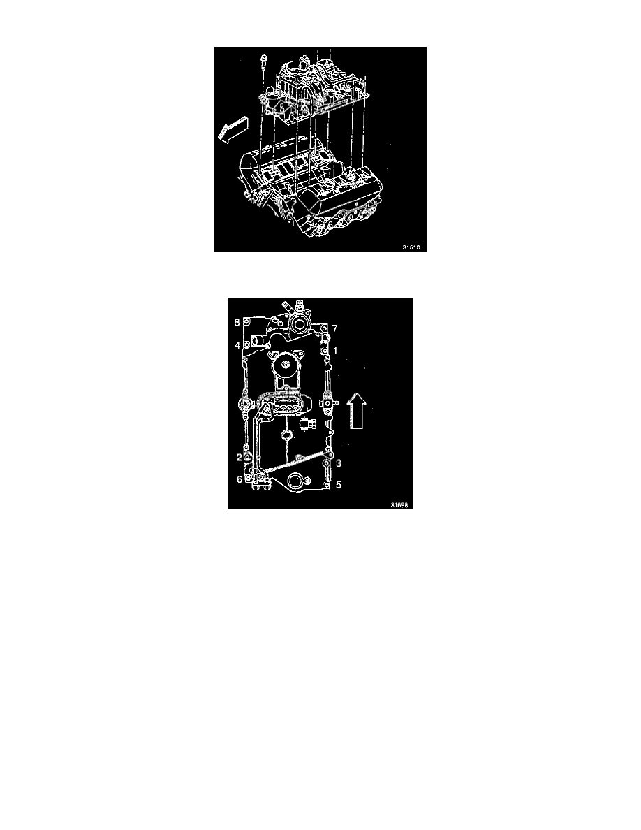
3. Install the lower intake manifold to the engine.
4. Apply sealer, GM P/N 1052080 or equivalent, to the lower intake manifold bolts.
5. Install the lower intake manifold bolts. Tighten the bolts in sequence.
^
Tighten the first sequence to 3 Nm (26 inch lbs.).
^
Tighten the second sequence to 12 Nm (106 inch lbs.).
^
Tighten the final sequence to 15 Nm (11 ft. lbs.).
6. Install the generator bracket bolt next to the thermostat housing.
7. Connect the coolant bypass hose.
8. Install the EGR valve.
9. Connect the upper radiator hose at the thermostat housing.
10. Connect the heater hose at the lower intake manifold.
11. Connect the fuel supply and the return lines at the rear of the lower intake manifold.
12. Connect the wiring harness and the brackets.
13. Connect the throttle cable, cruise control cable and the bracket.
14. Install the transmission oil level indicator tube.
15. Install the EGR tube, the clamp, and the bolt.
16. Install the PCV valve and the Vacuum hoses.
17. Install the air conditioning compressor, the bracket, and the accessory drive bracket.
18. Install the distributor.
^
Note the relationship of the distributor housing and the rotor made at disassembly.