
C 2500 Truck 2WD V8-305 5.0L VIN M SFI (1997)
Trailer Lamps: Description and Operation
Two trailer harnesses are available: heavy-duty trailer towing (UY7) and camper (UY1).
The option UY7 trailer harness is for heavy-duty towing applications. A 30-amp fused battery feed wire and auxiliary circuit routes from the
cowl-mounted junction block, along the body side rail, to the rear bumper crossmember. The harness for the brake/parking lamps is spliced from the rear
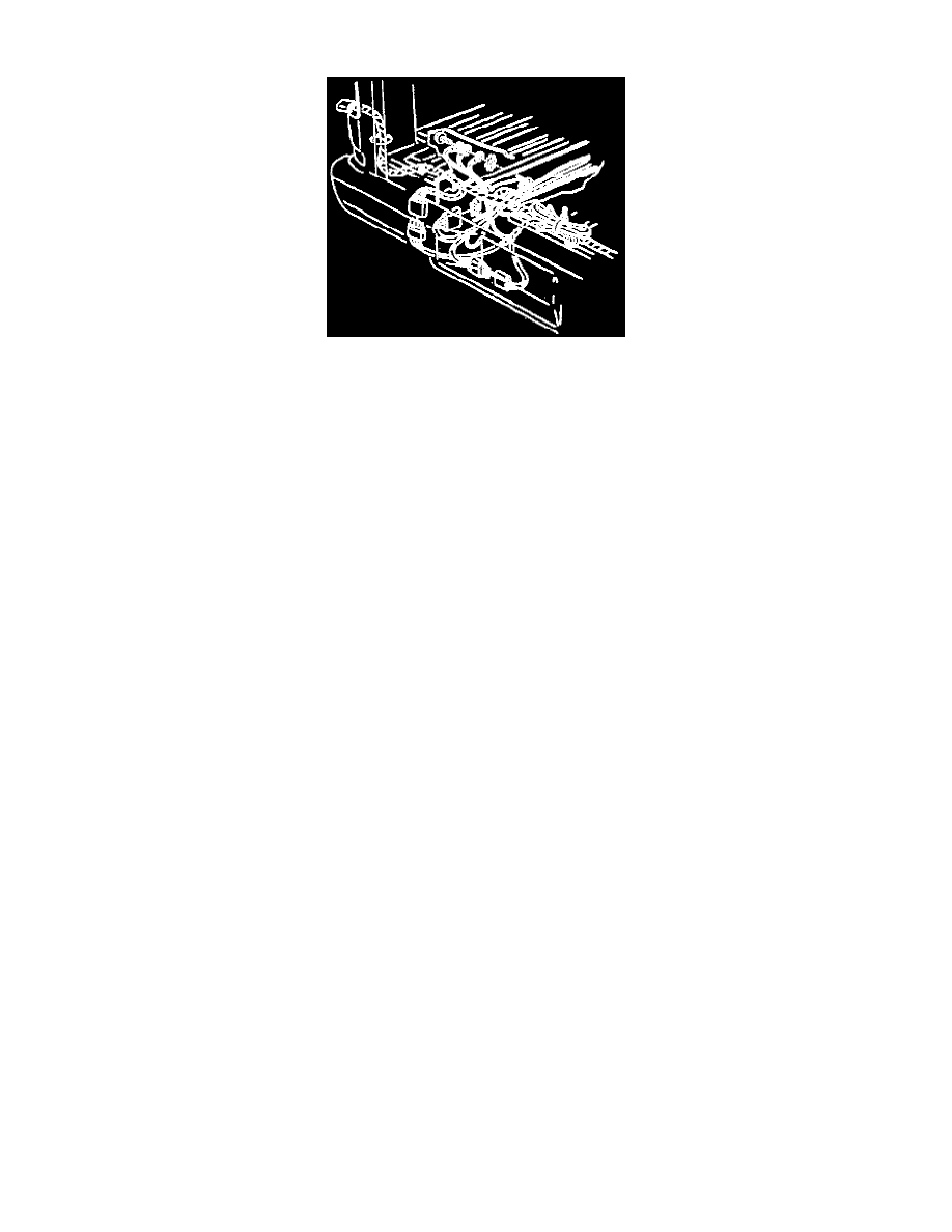
lamp harness. The harness is located at the rear bumper crossmember and is bound with a plastic strap (Figures 2 and 3). The wiring harness is wrapped
with tape to prevent short circuits.
The functions of the seven wires are:
1. Red-30 amp fused battery feed.
2. Dark Blue An auxiliary circuit.
3. Brown-Tail and license lamps.
4. Light Green-Backup lamps.
5. Dark Green-Right turn signal and stoplamp.
6. Yellow-Left turn signal and stoplamp.
7. White-Ground.
This option does not include a connector at the end of the harness. It must be wired after production by a qualified technician.
Attach the trailer harness wiring to the trailer. Then strap it to the vehicle frame rail in such a way that enough slack is left in the harness to prevent
bending, binding, or breakage of the wiring. Do not allow the harness to drag on the ground. Tape or strap the trailer portion of the harness (if used) to
the tongue of the trailer. This will prevent the harness from dragging on the ground.
When the harness is not being used, wrap it together and bind it with a tie strap to keep it from being damaged. Store the harness behind the rear bumper
on the fuel tank strap with a band or tie strap.
The second wiring harness option is the UY1 camper wiring harness, and is also spliced from the rear lamp harness.
This harness is for the brake/parking lamps and an auxiliary power feed. The harness is located in the front stake pocket during production and is
wrapped and bound with a plastic strap. This option uses a single harness and a connector using five wires.
The functions of the wires are:
1. Dark Blue-A 30-amp fused auxiliary power circuit. The other end of this wire is taped to the wiring near the junction block on the cowl.
2. Dark Green-Right turn signal and stoplamp.
3. Yellow-Left turn signal and stoplamp.
4. Brown-Taillamps.
5. White-Ground.
Route the trailer harness wiring between the frame and bumper, or camper and body, in such a way that enough slack is left in the harness to prevent
bending, binding, or breakage of the wiring. Do not allow the harness to drag. Tape or strap the trailer portion of the harness (if used) to the vehicle. This
will prevent the harness from dragging.
When the wiring is not being used, wrap the harness together and bind it with a tie strap to keep it from being damaged.