
C 2500 Truck 2WD V8-305 5.0L VIN M SFI (1997)
Alternator: Description and Operation
CS-144 Generator
General
CS-144 Generator
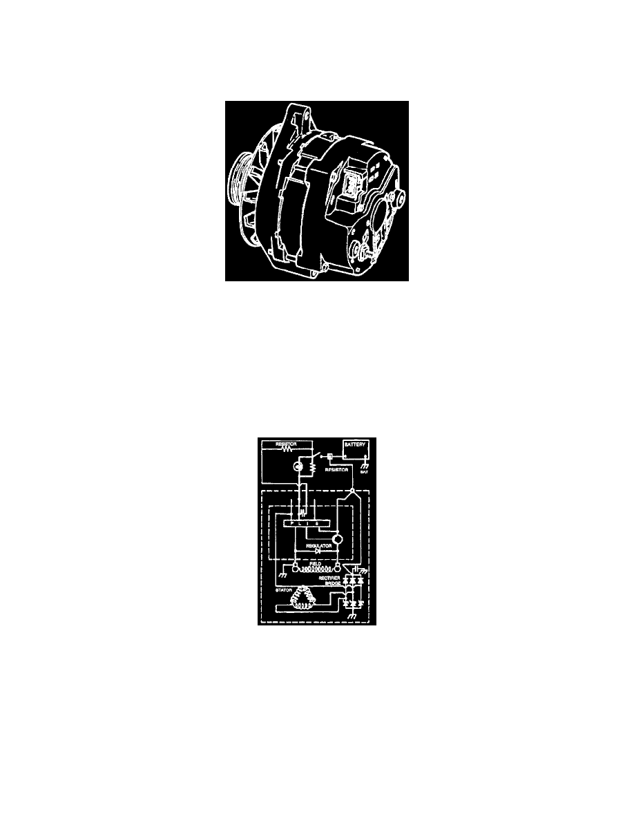
The CS-144 generator with integral regulator shown in image above, features a high ampere output per pound of weight. It does not use a diode trio. The
delta stator, rectifier bridge, and rotor with slip rings and brushes, are electrically similar to other CS-series generators. CS stands for Charging System,
and 144 indicates the outside diameter of the stator laminations in millimeters. The bearings are sealed with lifetime lubrication in both end frames. No
periodic maintenance is required.
Operating Principles
Regulator voltage setting varies with temperature and limits system voltage by controlling rotor field current. When the field current is on, the regulator
actually switches rotor field current on and off at a fixed frequency of about 400 cycles per second to help control radio noise. By varying on-off time,
correct average field current for proper system voltage control is obtained. At high speeds, the on-time may be 10 percent and the off-time 90 percent.
At low speeds, with high electrical loads, on-off time may be 90 percent and 10 percent respectively.
Generator Schematic
A basic wiring circuit for the "PLIS" regulator is shown image above. The "P" terminal connects to the stator. The "S" terminal may be connected
externally to the battery to monitor voltage and make sure the regulator maintains an adequate voltage level to charge the battery. If the "S" terminal is
not connected externally, integrated circuits in the regulator are used for sensing voltage.
Both the "L" and "I" terminals serve to turn on the regulator and allow field current to flow when the switch is closed. The "I" terminal may be connected
either directly to the switch, or through a resistor. The "I" circuit may be used with or without anything connected to the "L" circuit and with or without
anything connected to the "L" terminal. When used, the "L" terminal must be connected through an external resistor, such as the charging system
indicator lamp. When a generator fault is detected (voltage too high or too low, or no rotation), the regulator grounds the "L" terminal and activates the
indicator lamp.