
C 2500 Truck 2WD V8-350 5.7L (1988)
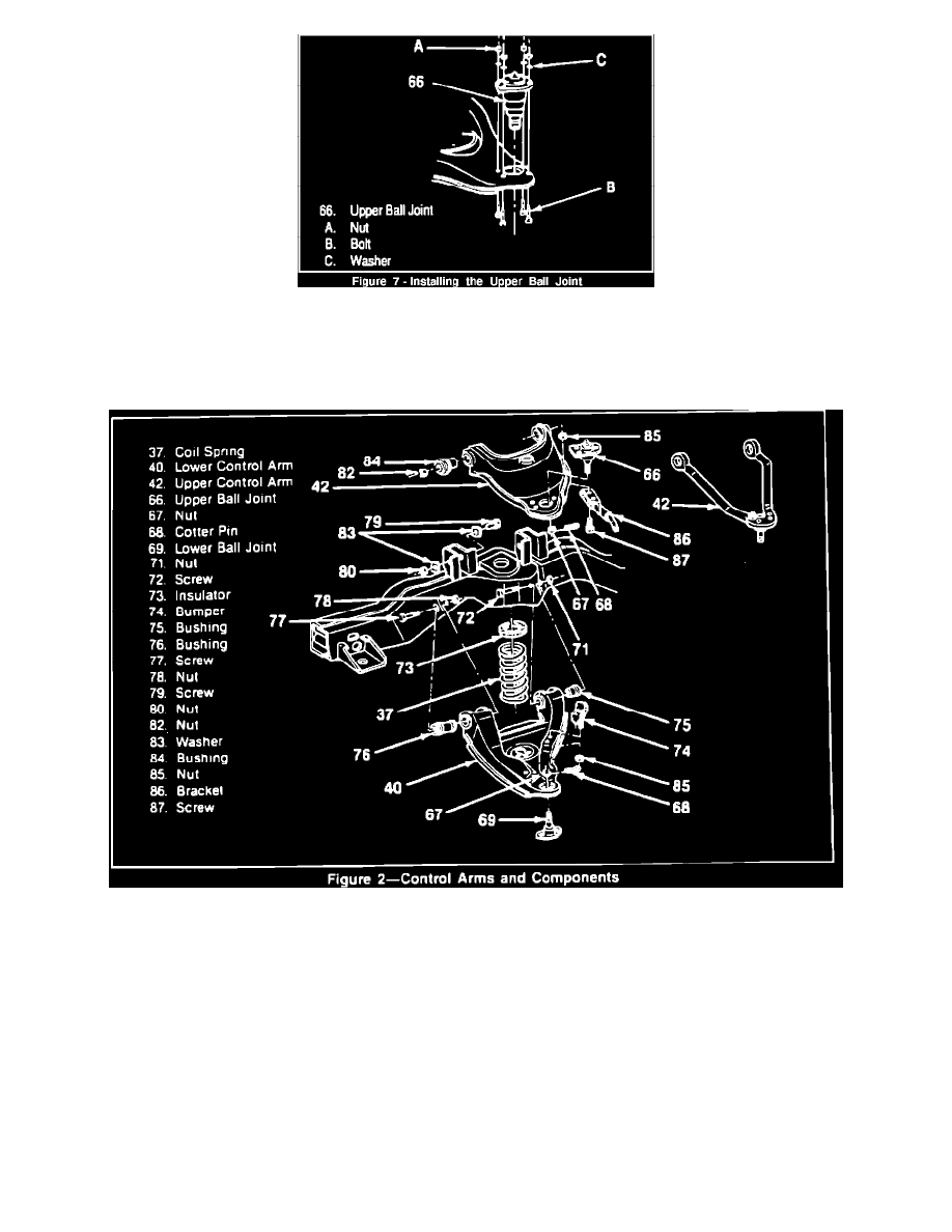
Figure 7
a. Position four attaching bolts (pointing upward), washers and nuts (Figure 7).
b. Tighten nuts (A) to 23 N-m (17 lb.ft.).
Figure 2
11.
Install new upper ball joint (Fig. 2, 66) to knuckle.
12.
Install upper stud nut (Fig. 2, 67) and new cotter pin (Fig. 2, 68).
a. Tighten stud nut (Fig. 2, 67) to 100 N-m (75 lb.ft.).
b. Align slot in stud nut with hole in stud by tightening stud nut.
c. Bend pin ends against stud nut.
13.
Install brake rotor and caliper.
14.
Install brake line support (Fig. 2, 86) to upper control arm (Fig. 2, 42).