
C 2500 Truck 2WD V8-379 6.2L DSL VIN J FI (1992)
Throttle Position Sensor: Adjustments
*** UPDATED BY TSB# 932486C, DATED JUNE 1993
1. Remove air cleaner assembly and related hoses.
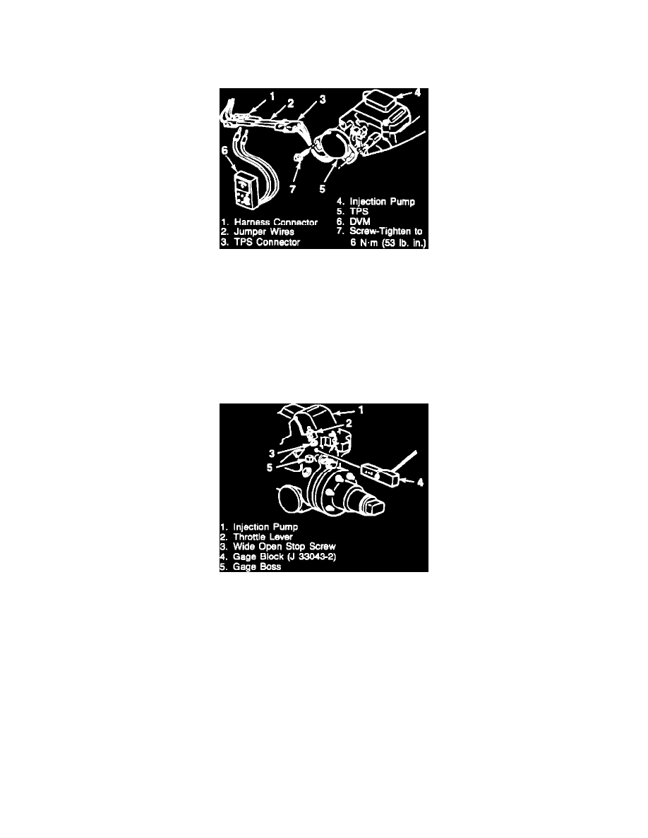
Connecting Digital Multimeter
2. Disconnect the TPS connector and insert jumper wires between TPS and harness. Jumpers can be made using terminals P/N 12052843 and
12052844. Three jumper wires or their equivalent will be necessary.
3. Turn key to "ON", engine not running.
4. Using a digital multimeter J 34029-A or equivalent, measure the voltage from the TPS connector terminals "A" to "C". This is the voltage
reference.
5. Multiply the voltage ratio number 0.33 with the voltage reference number from step #4. The resulting product is the desired TPS voltage
setting.
Example: 0.33 (voltage ratio) x 5.00 volts (voltage reference) = 1.65 (desired voltage setting)
Installing Gage Block
6. Insert a 0.646 side of the TPS/VRV gage block, P/N J 33043-2, between the gage boss on the injector pump and the wide open stop screw on
the throttle lever.
7. Rotate the throttle lever toward the wide open position so the gage block is held firmly in place.
8. Measure the voltage between terminals "B" and "C". This is the TPS voltage. It must be within +/- 1 percent of the desired TPS voltage setting
from step #5.
Example: For a desired voltage setting of 1.65 volts, tolerance = 0.01 (1 percent) x 1.65 volts (desired voltage setting) = 0.02 volts
(tolerance). Therefore, the TPS voltage setting must be between 1.63 volts and 1.67 volts (1.65 +/- 0.02).
9. If tolerance is within tolerance, then proceed to step #12.
10. To adjust the TPS, loosen the two attaching screws and rotate the TPS to the counter-clockwise position (facing sensor). Rotate the TPS
clockwise until the desired TPS voltage setting (from step #5) is obtained. Sensor hysteresis requires clockwise rotation to correctly set the
sensor.
11. When the correct voltage is obtained, hold TPS in this position and tighten the TPS attaching screws.
Torque Value:
6 Nm (53 in lb)
12. Release throttle lever and allow it to return to the idle position. Open the throttle lever back against the gage block and check that TPS voltage
is within 1 percent of the desired TPS voltage setting, see step 8 for voltage range. Return to step 10 if adjustment necessary.