
C 2500 Truck 2WD V8-6.5L DSL Turbo VIN S (1997)
Technical Service Bulletin # 77-61-15
Date: 971001
Engine - Revised Crankshaft and Bearings Installation
File In Section: 6 - Engine
Bulletin No.: 77-61-15
Date: October, 1997
SERVICE MANUAL UPDATE
Subject:
Section 6 - Engine Mechanical - Crankshaft and Bearings Installation
Models:
1997 Chevrolet and GMC C, K, G, and P Models
with 6.5L Diesel Engines (VINs S, Y, F - RPOs L56, L57, L65, L65-CMT)
The engine block for both production and for GMSPO (target engines) engine assemblies has been modified. The crankshaft bearing cap retaining bolt
diameter at positions 2, 3, and 4 (outer bolts only) have been changed from 12 mm to 10 mm. This requires the use of a revised torquing sequence. Prior
to installing the crankshaft in any 6.5L engine, verify the type of bolts used for the crankshaft bearing caps. For engines built prior to March 13, 1997 (all
bolts are 12 mm), use the vehicle model year Service Manual's existing procedure. For engines built after March 13, 1997 (all inner bolts are 12 mm,
outer bolts at positions 1 and 5 are 12 mm, and outer bolts at positions 2, 3, and 4 are 10 mm), use the information provided in this bulletin. This
information is also available in the 1998 Service Manual.
Crankshaft,Bearings Install.(C,K, G Trks, RPOs L65,L65-CMT)
Crankshaft and Bearings Installation (C, K, and G Trucks, RPOs L56, L65, L65-CMT)
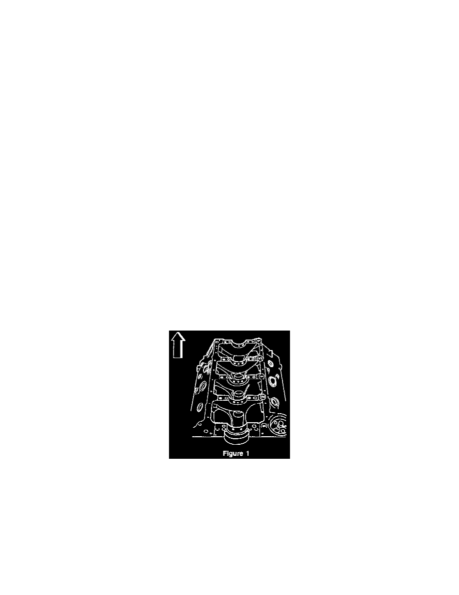
There are five crankshaft bearings numbered 1 through 5, as viewed from the front of the engine. There is an arrow on each bearing cap that points
toward the front of the engine. The center crankshaft bearing, number three, is the thrust bearing.
The upper crankshaft bearing inserts all have an oil groove and a oil gallery hole from the block in the center of the groove. The upper crankshaft bearing
inserts also have additional holes in the groove at 10 o'clock and 2 o'clock to provide oil to the oil spray nozzles. The oil spray nozzles are mounted in
the crankshaft bearing bulkheads. The lower bearing inserts do not have an oil groove or holes. During initial assembly, the crankshaft bearings are
select4itted to each of the five crankshaft bearing bores. The total diameter size range of crankshaft bearing bores 1 through 5 is 79.826 - 79.850 mm
(3,145 - 3.146 in). This range divides into three sizes, represented by the size numbers 1, 2 or 3.
The proper size number is then stamped on the pan rail at the corresponding crankshaft bearing bulkhead. The crankshaft is color-marked in red/orange,
blue, or white, near each crankshaft bearing journal. Cross-referencing the size number on the pan rail with the color on the crankshaft indicates the
proper bearing selection (See Figure 1).
Crankshaft Bearings are available in standard 0.013 mm (0.0005 in.) and 0.026 mm (0.0010 in.) undersized for select fining, in order to attain proper
crankshaft bearing clearance.