
C 2500 Truck 2WD V8-6.5L DSL Turbo VIN S (1997)
e. The T-bolt head and bridge must line up horizontally with the knockout; the bridge should span the knockout without interfering with the
knockout procedure.
f.
Tighten the T-bolt head against the knockout by turning the nut at the opposite end using a socket and torque wrench.
g. An open end or adjustable wrench may be needed to prevent the T-bolt from losing horizontal alignment with the knockout.
CAUTION: Do not subject the tool to more than 100 Nm (75 ft. lbs.) torque. Exceeding the recommended torque may damage the tool
and/or the bracket.
h. If the torque limit on the T-bolt is met and the knockout does not break free, use a die grinder of appropriate size. Using the stamped outline as
a guide, remove the knockout. (Remove the wax coating in the knockout area to make the perforation lines more visible).
i.
If the outline is not visible, use the T-bolt head installed horizontally, as a template, and scribe the frame bracket.
j.
Repeat the procedure on the other upper control arm frame bracket.
INSTALLATION
CAUTION: Always use the correct fastener in the proper location. When you replace a fastener, use ONLY the exact part number for that
application. The manufacturer will call out those fasteners that require a replacement after removal. The manufacturer will also call out the fasteners
that require thread lockers or thread sealant. UNLESS OTHERWISE SPECIFIED, do not use supplemental coatings (paints, greases, or other
corrosion Inhibitors) on threaded fasteners or fastener joint interfaces. Generally, such coatings adversely affect the fastener torque and joint clamping
force, and may damage the fastener. When you install fasteners, use the correct tightening sequence and specifications. Following these instructions
can help you avoid damage to parts and systems.
Install or connect the following:
1. Upper control arm (45) into frame brackets (44).
2. Bolts (48) and cams (49) through frame brackets (44), and control arm (45).
3. Cams (49) and nuts (50). Install cams with radius toward frame brackets.
4. Partially tighten nut (50).
5. Front wheel assemblies.
6. Alignment machine heads.
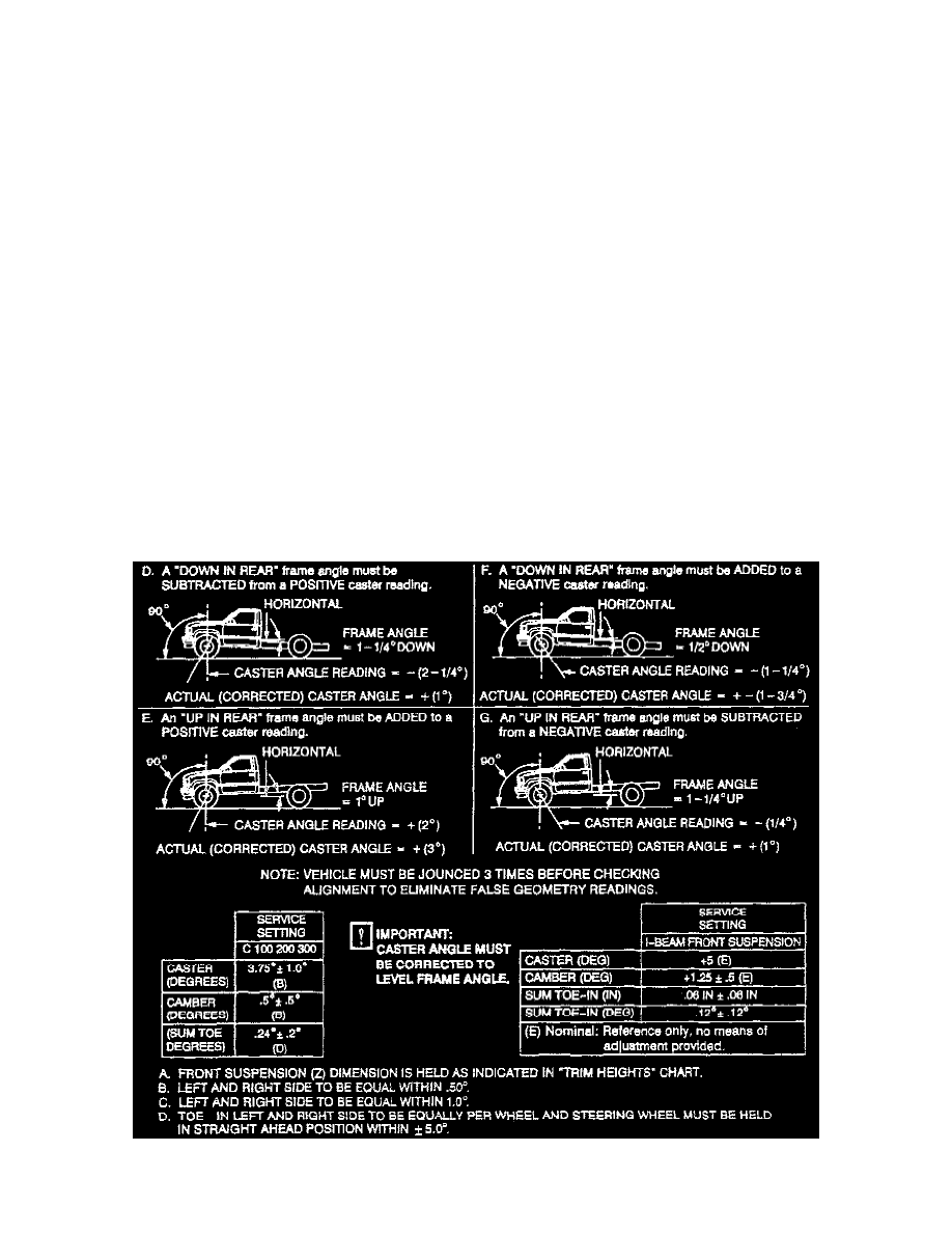
NOTE: Check image for special requirements and alignment adjustments. Check vehicle ride height. Verify alignment specifications before
proceeding.