
C 2500 Truck 2WD V8-6.6L DSL Turbo VIN 1 (2001)
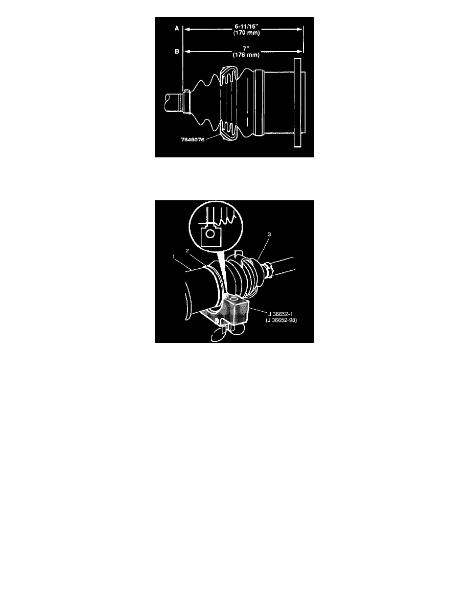
14. Check the inboard stroke position.
^
Use measurement A for the K1 5 models.
^
Use measurement B for the K25 models.
15. Position the inboard end (tri-pot end) of the halfshaft assembly in J 36652.
16. Install the top half of the proper size tool on the lower half of the tool. For K1 5 models, use J 36652-98.
17. For K25 models, use J 36652-1.
18. Align the swage ring (2) and the swage ring clamp.
19. Insert the bolts.
^
Hand tighten the bolts in J 36652 until the bolts are snug.
Important: Align the following during this procedure:
^
The tri-pot seal (3)
^
The housing (1)
^
The swage ring (2)
^
Tighten each bolt 180 degrees at a time. Alternate between the bolts until both sides of the top half of J 36652 touch the bottom half of the J
36652.
20. Loosen the bolts and remove the halfshaft assembly from J 36652.