
C 30 P/U 2WD V8-379 6.2L DSL (1985)
Throttle Valve Cable/Linkage: Testing and Inspection
Diagnosis Procedure
If the T.V. cable is broken, sticky, misadjusted or incorrect part of the model, the vehicle may exhibit various malfunctions.
Sticking or binding T.V. linkage can result in delayed or full throttle shifts. The T.V. cable must be free to travel to the full throttle position and return
to the closed position without binding or sticking.
Some binding or sticking of the T.V. cable and associated parts may only occur with the engine running and will not be noted or obtained with the
engine off.
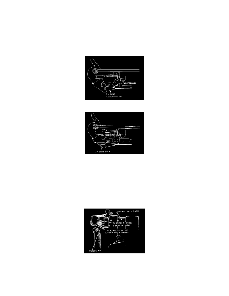
Figure 7A-7 T.V. Cable At Carburetor Lever
Figure 7A-8 Sticking T.V. Cable
Inspection of the T.V. linkage for sticking or binding should be made with engine running at idle speed, with the transmission selector in neutral and
the parking brakes set. Pull the T.V. cable full travel through the cable terminal and then release the cable; it should return to the closed throttle
position against the cable terminal (Figure 7A-7). If the T.V cable sticks, and remains ahead of the cable terminal (Figure 7A-8), it may be caused by
one or more of the following:
1. Sharp bends or a damaged T.V. cable housing. Correct by rerouting the cable or replace if it is required.
2. Sharp end or burr on the T.V. link, dragging in the T.V. cable housing. Correct by making end smooth, using a file or stone. DO NOT
SHORTEN LINK.
3. Bent T.V. link. Correct by straightening or replace as required.
Figure 7A-9 Alignment Of Throttle Lever And Bracket Assembly
4. Misalignment of the throttle lever and bracket assembly on the coiled pin in the control valve assembly (Figure 7A-9).
5. Damaged or binding throttle lever and bracket assembly. Correct by straightening or replace as required. (Typical)
6. Throttle lever spring unhooked or damaged. Correct by assembling the spring properly or replace the throttle lever and bracket as required.