
C 3500 HD Truck 2WD V8-8.1L VIN G (2002)
9. This step tests for continuity on the PTO Engage Signal circuit.
10. This step ensures that all of the PCM conditions for engaging the PTO are met.
11. This step tests for ground on the Battery Positive Voltage circuit.
12. This step tests for a ground on the Battery Positive Voltage circuit.
13. This step tests for ground on the PTO Supply-Voltage circuit.
14. This step tests for ground on the Ignition 3 Voltage circuit.
17. This step tests for ground on the Power Take-Off Switch Output Enable circuit.
18. This step tests for voltage at the Ignition 3 Voltage circuit.
19. This step tests the PTO Relay.
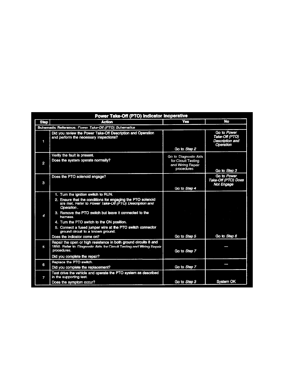
Power Take-Off (PTO) Indicator Inoperative
CIRCUIT DESCRIPTION
This symptom chart will aid in diagnosing a failed Power Take-Off (PTO) indicator. This diagnostic assumes that the PTO solenoid is functional and
only the indicator is failing to come on. When the ignition switch is in RUN, voltage should be present on the Ignition 3 Voltage circuit. When the
PTO switch is turned to ON, the LED will illuminate. The indicator has its own ground circuit. The LED and PTO solenoid have different ground
circuits. Therefore, the LED may be illuminated when the PTO solenoid is disengaged.
TEST DESCRIPTION
Steps 1-7
The number below refers to the step number on the diagnostic table.
4. This step tests the ground circuit.