
C 3500 Truck 2WD V8-5.7L VIN R (1996)
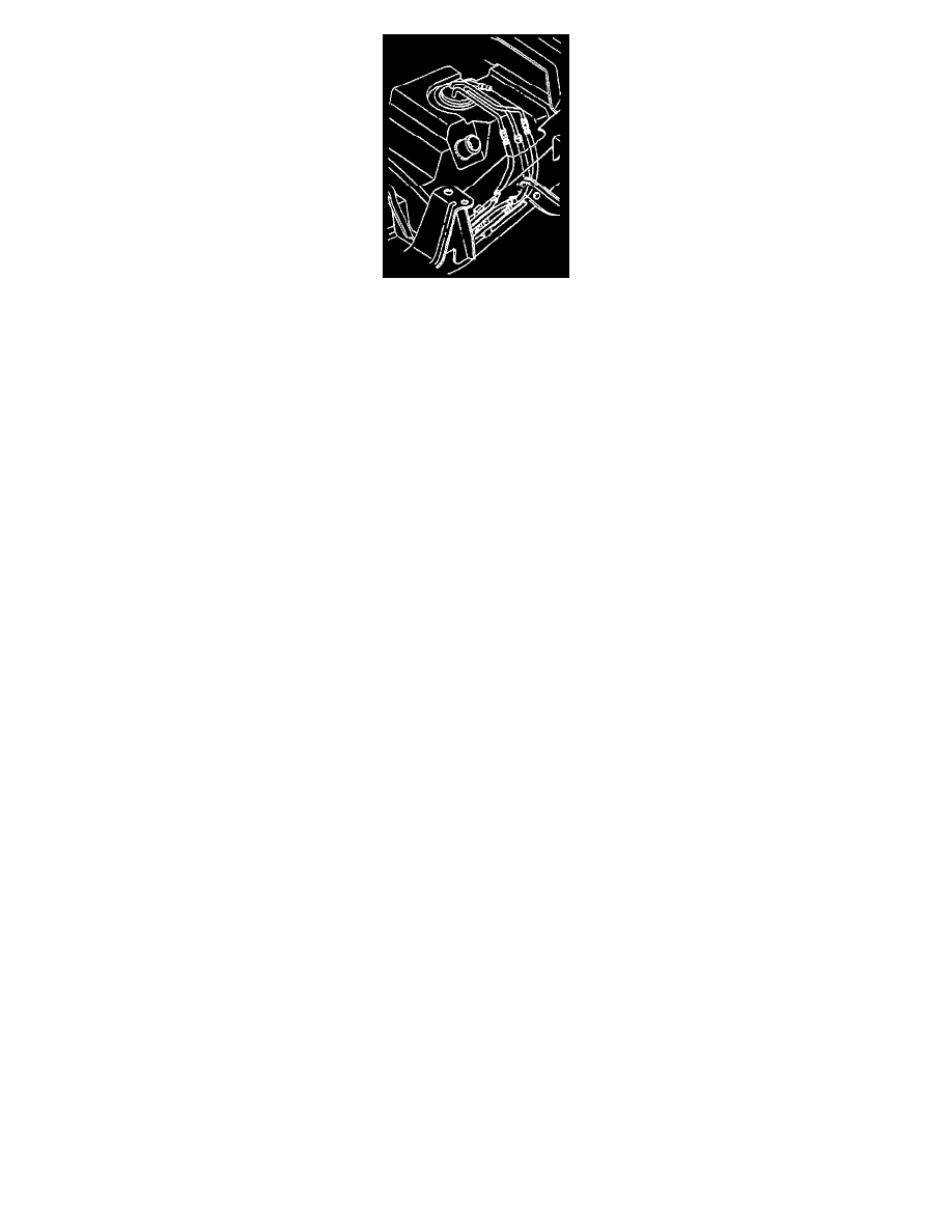
Diagram
Removal Procedure
NOTE: If the nylon pipes become kinked, and cannot be straightened, replace them.
-
Do Not attempt to repair sections of nylon pipes. If damaged, replace.
-
When replacing the vapor pipes, always replace them with original equipment or parts that meet GM specifications.
-
When replacing the vapor hoses, always replace them with original equipment or parts meeting GM specifications. Use only reinforced
fuel-resistant hose identified with the word Fluoroelastomer or GM 6163-M on the hose.
1. Remove the hardware retaining section of the pipe to be replaced. Note the location of attaching hardware for installation.
2. Remove the section of the pipe and hoses.
3. Inspect the hoses for cuts, swelling cracks and distortion. Replace as required.
4. Inspect the pipes for holes, kinks, and cracks. Replace the sections as required.
Installation Procedure
Important:
-
Follow the same routing as the original pipes and hoses.
-
Secure the pipes and hoses to prevent chafing.
1. Install the section of the pipe and hoses.
2. Install the hardware retaining section of the pipe being replaced.
Fuel Supply/Return/or Emission Pipe Service
FUEL SYSTEM CLEANING (PURGE FEED AND RETURN PIPES)
REMOVAL PROCEDURE
1. Disconnect the fuel feed and return pipes at the fuel injection unit. Refer to Fuel Hose and Pipes. See: Fuel Supply/Return/or Emission Pipe
Replacement
NOTE: Inspect the in-line fuel filter for contamination. Replace the fuel filter if it is plugged.
2. Disconnect the in-line fuel filter. Refer to In-Line Fuel Filter. See: Fuel Filter/Service and Repair
NOTE: Use only oil free compressed air to blow out the fuel pipes.
-
If the in-line fuel filter is plugged, inspect the fuel tank internally and purge if necessary.
3. Clean the fuel lines by applying air pressure in the opposite direction of fuel flow.
INSTALLATION PROCEDURE
1. Install a new strainer (if necessary) on the fuel sender assembly. Refer to Fuel Sender Assembly. See: Fuel Pump/Service and Repair
NOTE: Do not fold or twist the strainer when installing the sending unit. This action restricts fuel flow.
2. Install the fuel sender assembly with a new seal into the fuel tank.
3. Install the fuel tank. Refer to Fuel Tank Assembly. See: Fuel Tank/Service and Repair
4. Disconnect the fuel feed pipe at the fuel injection unit.
5. Connect a hose to the fuel feed pipe at the fuel injection unit. Insert the other end of the hose into a 3.8 liter (one gallon) fuel can.