
C 3500 Truck 2WD V8-6.6L DSL Turbo VIN 1 (2002)
9. Position the outlet heater hose.
10. Install the fuel filter mounting bolts.
11. Install the fuel injection control module.
12. Install the bolt (2) retaining the heater hose bracket to the generator bracket.
-
Tighten the bolt to 21 Nm (15 ft. lbs.).
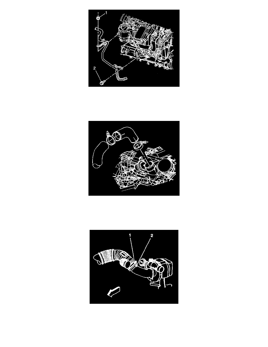
13. Remove the tape from the charged air cooler outlet duct to charge air cooler pipe opening and the intake manifold tube opening.
14. Position the hose on the pipe and the intake manifold tube.The hose is marked ENG for the intake manifold tube end and DUCT for the pipe end.
15. Install the clamps and position as shown in order to allow the proper clearances.
-
Tighten the clamps to 6 Nm (53 inch lbs.).
16. Install the charged air cooler inlet duct to the turbocharger.
Important: The outlet duct must be fully seated against the positive stop feature on the turbocharger inlet.
17. Install the outlet duct to the turbocharger.
18. Align the outlet duct alignment indicator (1) to the turbocharger alignment indicator (2).