
Camaro V6-3.8L VIN K (1995)
Harmonic Balancer - Crankshaft Pulley: Service and Repair
This article has been updated with bulletin No.: 57-61-32.
CRANKSHAFT BALANCER
There has been a running design change in the crankshaft balancer. This change affects 3800 engines built late in the 1995 model year (L27 and L36)
and all of 1996 model year (L36 and L67). Refer to the following procedure using (J 38197-MOD) for the revised design crankshaft balancer. The
crankshaft balancer designs can be easily identified by the following:
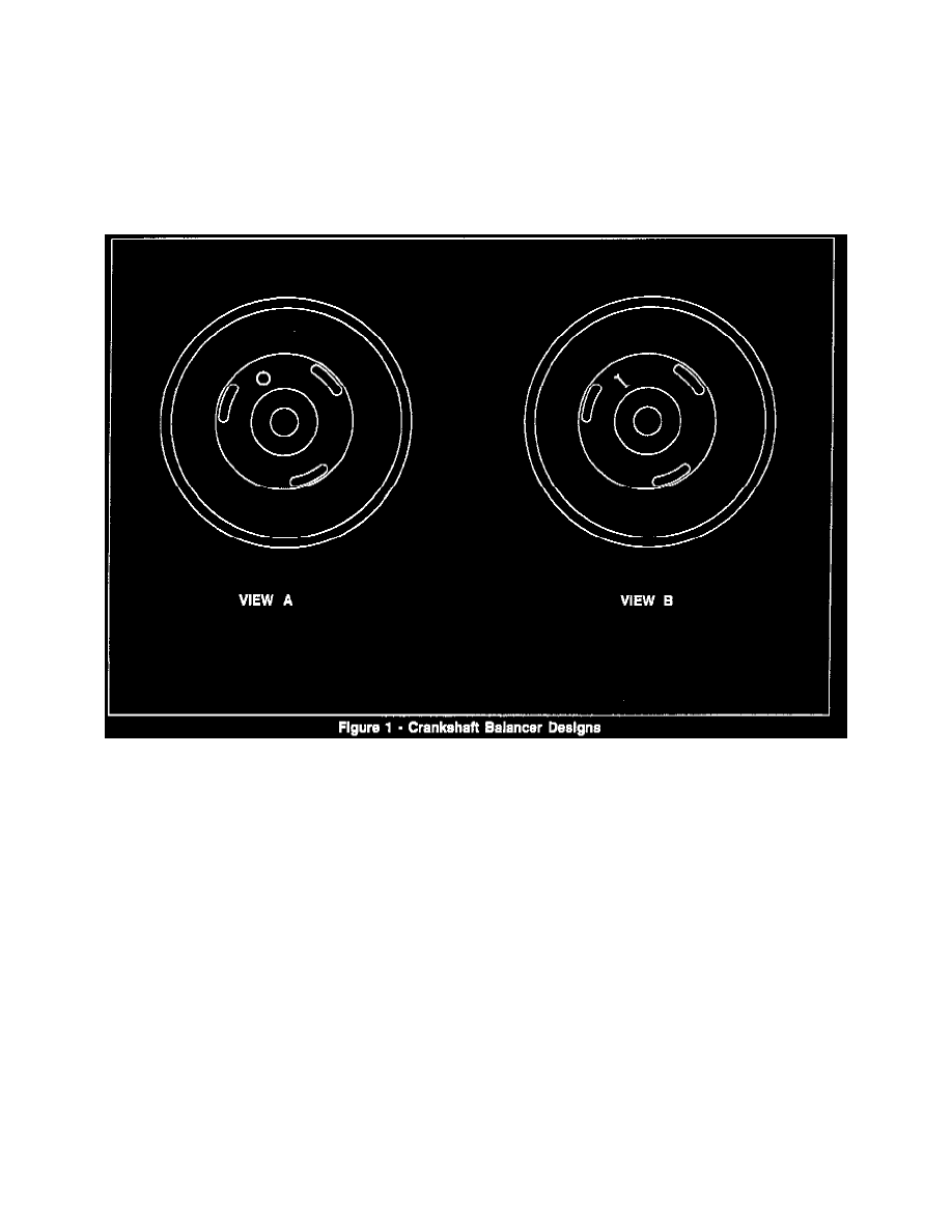
PREVIOUS CRANKSHAFT BALANCER DESIGN
Has a dimple stamped in the face of the crankshaft balancer. Figure 1 View B. This dimple aids in the alignment of J 38197-2 and also identifies the
crankshaft key location in relation to the slot in the crankshaft balancer. The special tool (J 38197) and the service procedure used to service the
previous design crankshaft balancer have not been revised. Refer to applicable service manual and section for correct service procedures.
REVISED CRANKSHAFT BALANCER DESIGN
Has a round hole drilled in the face of the crankshaft balancer. Figure 1 View A. This hole does not aid in the alignment of J 38197-2, like the dimple
on the previous designed crankshaft balancer. The hole is used to identify the crankshaft key location in relation to the slot in the crankshaft balancer.
The special tool (J 38197) has been revised to reflect the design changes and the new tool is J 38197-MOD. (If you already have J 38197 it is
necessary to only order the J 38197-MOD). The revised crankshaft balancer requires the use of three bolts (J 38197-4), these bolts are 1/4 inch longer
than the previous design. J 38197-4 are silver in color while the previous tool uses black bolts.
J 38197-4 should not be used to service the previous design crankshaft balancer as damage to the balancer may occur by using the longer bolts.
The revised crankshaft balancer may have burrs on the slotted access holes that do not allow the proper alignment of J 38197. If burrs are present,
remove them by using one of the following methods:
^
File access hole using rat-tail file in proper location.
^
Drill access hole using drill in proper location.
^
Bend access hole using screw driver in proper location.
REVISED CRANKSHAFT BALANCER SERVICE PROCEDURE
TOOLS REQUIRED:
^
J 36660 Torque Angle Meter
^
J 37096 Flywheel Holding Tool
^
J 38197-A and J 38197-MOD Crankshaft Balancer Puller
^
J 38197-A Includes: