
Camaro V6-3.8L VIN K (1995)
Heated Glass Element: Diagnostic Trouble Code Tests and Associated Procedures
Circuit Operation
When the Ignition Switch is turned to "RUN," voltage is applied from HVAC Fuse 3 to the Rear Defogger Switch. When the Rear Defogger Switch is
turned to "ON," voltage is momentarily applied to the Rear Defogger Solid State Timer through CKT 241. With voltage applied to the Rear Defogger
Timer On/Off Input, the Solid State Timer will energize the Internal Relay which applies voltage to the Rear Defogger Grid. The Relay remains closed
until the defog cycle is complete or the Rear Defogger Switch/Timer is turned "OFF.
When the internal contacts of the Rear Defogger Relay are closed, voltage from Circuit Breaker 12 is applied to the indicator and to CKT 293.
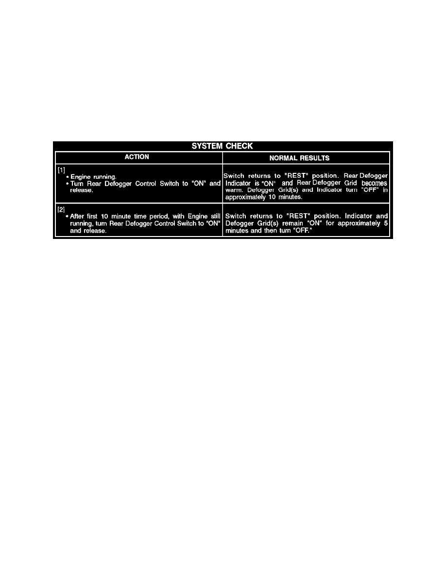
The Rear Defogger Switch contains an internal timer to control the time the internal contacts are closed. When the Ignition Switch is turned to "RUN"
and the Rear Defogger Switch is turned to "ON" for the first time, the defog cycle lasts 10 minutes. Further operation will result in 5 minute defog
cycles. The defog cycle is reset to 10 minutes when the Ignition Switch is turned to "OFF" and back to "RUN."
System Check
System Diagnosis - Rear Window Defogger & Heated Mirrors (SSE & SSEI Models)
^
Perform the System Check and refer to the Symptom Table for the appropriate diagnostic procedures. See: Symptom Related Diagnostic
Procedures/A Symptom Table - Rear Window Defogger & Heated Mirrors (SSE & SSEI Models) See: Symptom Related Diagnostic
Procedures/A Symptom Table - Rear Window Defogger & Heated Mirrors (SSE & SSEI Models)
Troubleshooting Hints
Perform before beginning System Diagnosis
1. Check HVAC Fuse 3. If open, refer to Chart #2. See: Symptom Related Diagnostic Procedures/Symptom Diagnostic Charts/Chart #2 Rear
Defogger Grid and Indicator Inoperative
2. Check Rear Defogger Grid for opens, refer to Body and Frame. See: Body and Frame
3. Check that grounds G200, G310 and G320 are clean and tight.
^
Check for a broken (or partially broken) wire inside of the insulation which could cause system malfunction but prove "GOOD" in a
continuity/voltage check with a system disconnected. These circuits may be intermittent or resistive when loaded, and if possible, should be
checked by monitoring for a voltage drop with the system operational (under load).
^
Check for proper installation of aftermarket electronic equipment which may affect the integrity of other systems (Refer to "Diagnostic
Aids/General Troubleshooting Procedures,"). See: Diagrams/Diagnostic Aids
^
Refer to System Diagnosis. See: System Diagnosis - Rear Window Defogger & Heated Mirrors (SSE & SSEI Models)